Method for manufacturing thermally-assisted magnetic recording head with light source unit

a technology of magnetic recording head and light source unit, which is applied in the direction of mounting head within the housing, special recording techniques, instruments, etc., can solve the problems of deterioration in the thermal stability of the magnetization, the head cannot write data to the magnetic recording medium, and the problem of more significant problems to be solved, and achieve high efficiency

Active Publication Date: 2011-10-06
TDK CORPARATION
View PDF4 Cites 41 Cited by
  • Summary
  • Abstract
  • Description
  • Claims
  • Application Information

AI Technical Summary

Benefits of technology

[0030]Further, in the method for manufacturing the thermally-assisted magnetic recording head according to the present invention, it is preferable that a first light source provided on the opposed-to-medium surface side of the slider is used to irradiate the waveguide with the first light, and the first light that has passed through the slider is detected by using a first photodetector provided on the back surface side of the slider, and that a second light source provided on the side opposite to the joining surface of the light source unit is used to irradiate the light source with the second light, and the second light that has passed through the light source unit is detected by using a second photodetector provided on the joining surface side of the light source unit. By using the alignment system including the first and second light sources and the first and second photodetectors, the above-described method for manufacturing the thermally-assisted magnetic recording head can be reliably performed with a high efficiency.

Problems solved by technology

However, the decrease in size of the magnetic grains raises a problem of degradation in thermal stability of the magnetization due to the decrease in volume.
As a result, the head cannot write data to the magnetic recording medium when the anisotropic magnetic field of the medium exceeds the write field limit.
However, from the beginning, more significant problem to be solved exists in where and how a light source with a sufficiently high output of light should be disposed inside a head.
However, the active alignment is a method of merely locating a two-dimensional optimum position and has the drawback of requiring a considerably long time for alignment.
In addition, power supply probes need to be applied to the electrodes of the light source in order to keep activating the light source during the alignment, which further increase the time required for the alignment.
Furthermore, a head structure and probing facilities which are required for the probing increase the manufacturing load.
Since the passive alignment uses such a recognition means which is, for example, inserted or drawn out, and since the added markers may have a positional error, the accuracy of the passive alignment tends to be low compared with the active alignment.
In addition, it is considerably difficult to find or add a marker for the passive alignment on the light-source unit during fabrication of a head having the “composite slider structure”.
Further, it is also difficult to perform an alignment with use of a contour of the joint object.
In fact, since processing accuracy, that is dimensional accuracy of the contour, is, for example, approximately ±5 μm, it is difficult to secure alignment accuracy within ±1 μm by using the positions of the contour as a standard.

Method used


Image

  • Method for manufacturing thermally-assisted magnetic recording head with light source unit
  • Method for manufacturing thermally-assisted magnetic recording head with light source unit
  • Method for manufacturing thermally-assisted magnetic recording head with light source unit

Examples


Embodiment Construction

. 7 shows a schematic view for explaining steps S1, Ss2 to Ss4, and SL2 to SL4 (FIG. 6) in one embodiment of the method for manufacturing the thermally-assisted magnetic recording head according to the present invention;

[0045]FIGS. 8a and 8b show schematic views for explaining steps S1, Ss2 to Ss4, and SL2 to SL4 (FIG. 6) in one embodiment of the method for manufacturing the thermally-assisted magnetic recording head according to the present invention;

[0046]FIGS. 9a to 9d show schematic views illustrating step 5 (FIG. 6) of an embodiment of the method for manufacturing the thermally-assisted magnetic recording head according to the present invention; and

[0047]FIG. 10 shows a schematic views illustrating step 6 (FIG. 6) in an embodiment of the method for manufacturing the thermally-assisted magnetic recording head according to the present invention.

DESCRIPTION OF THE PREFERRED EMBODIMENTS

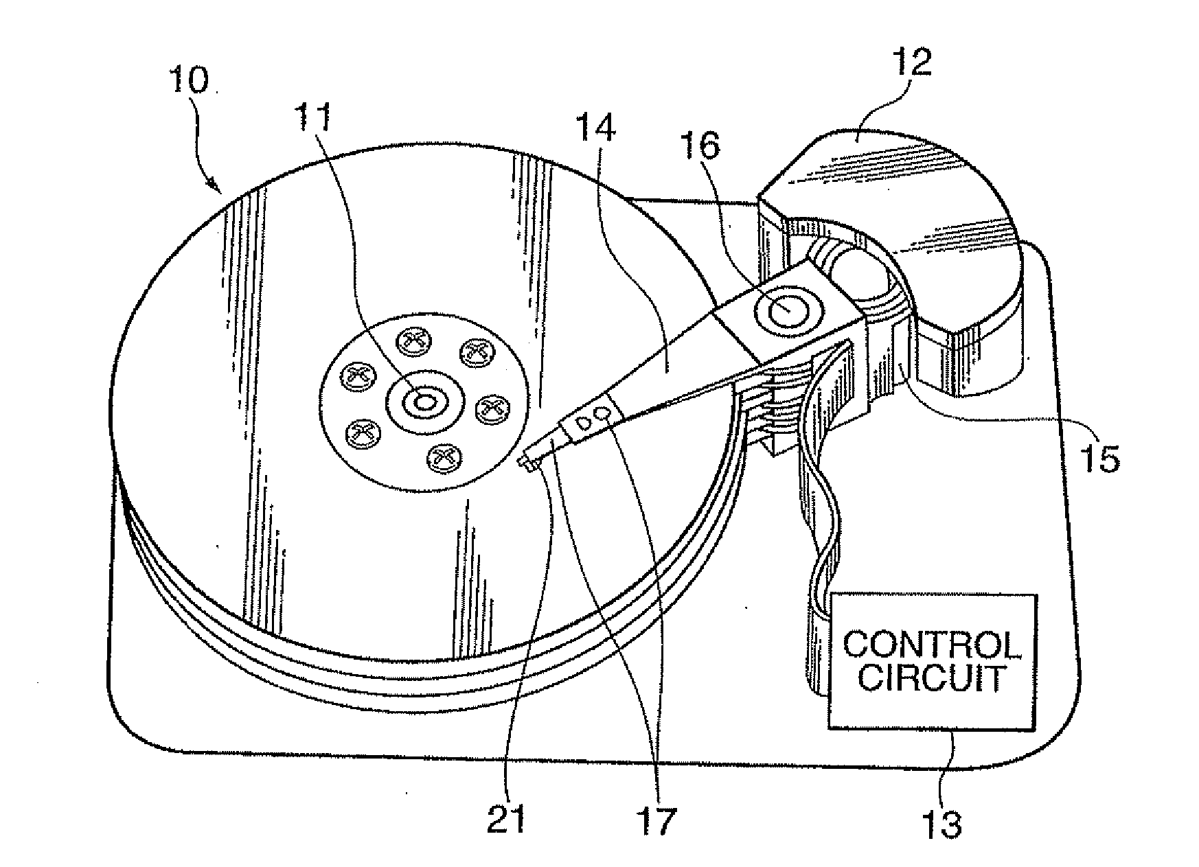
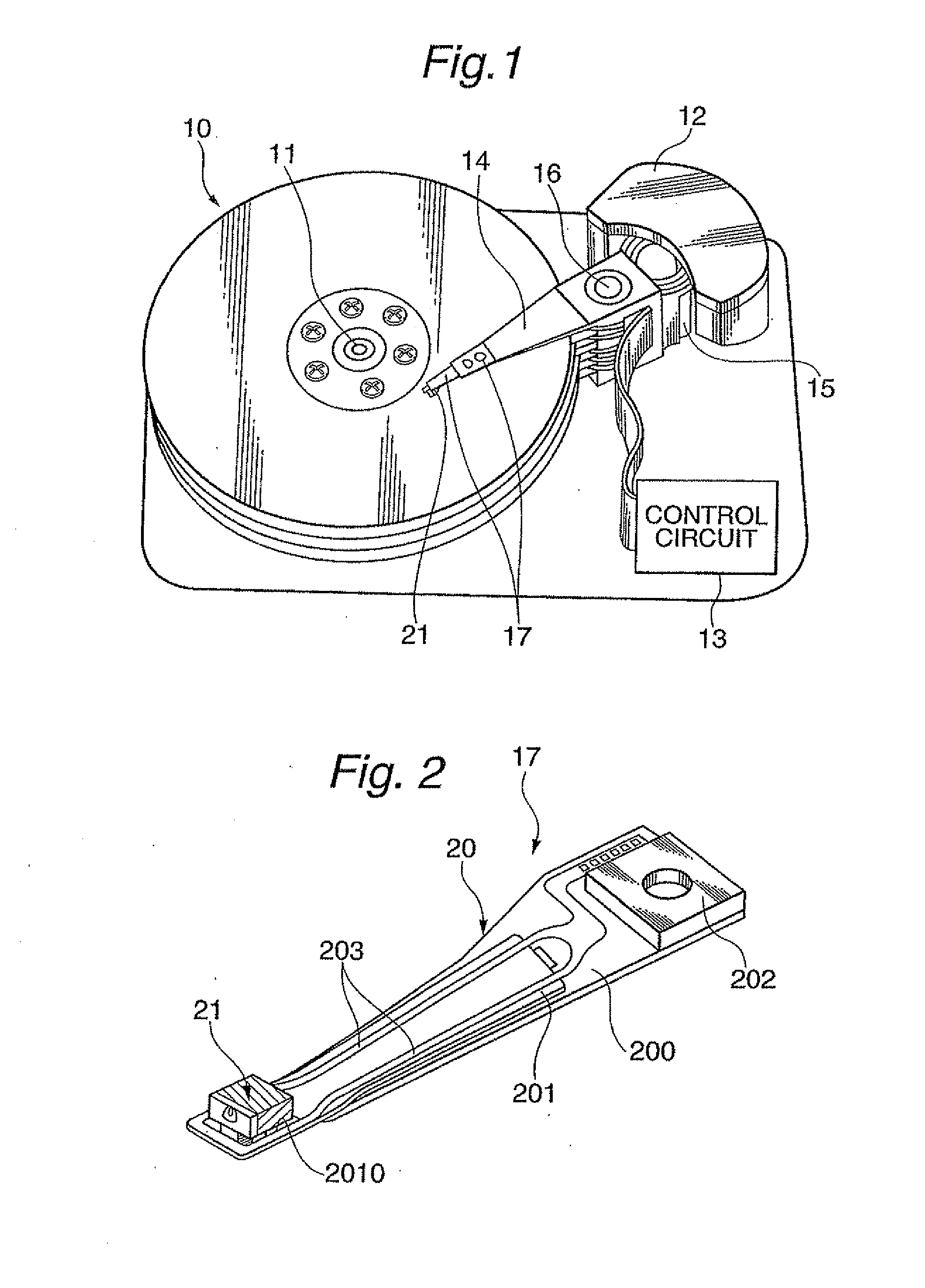
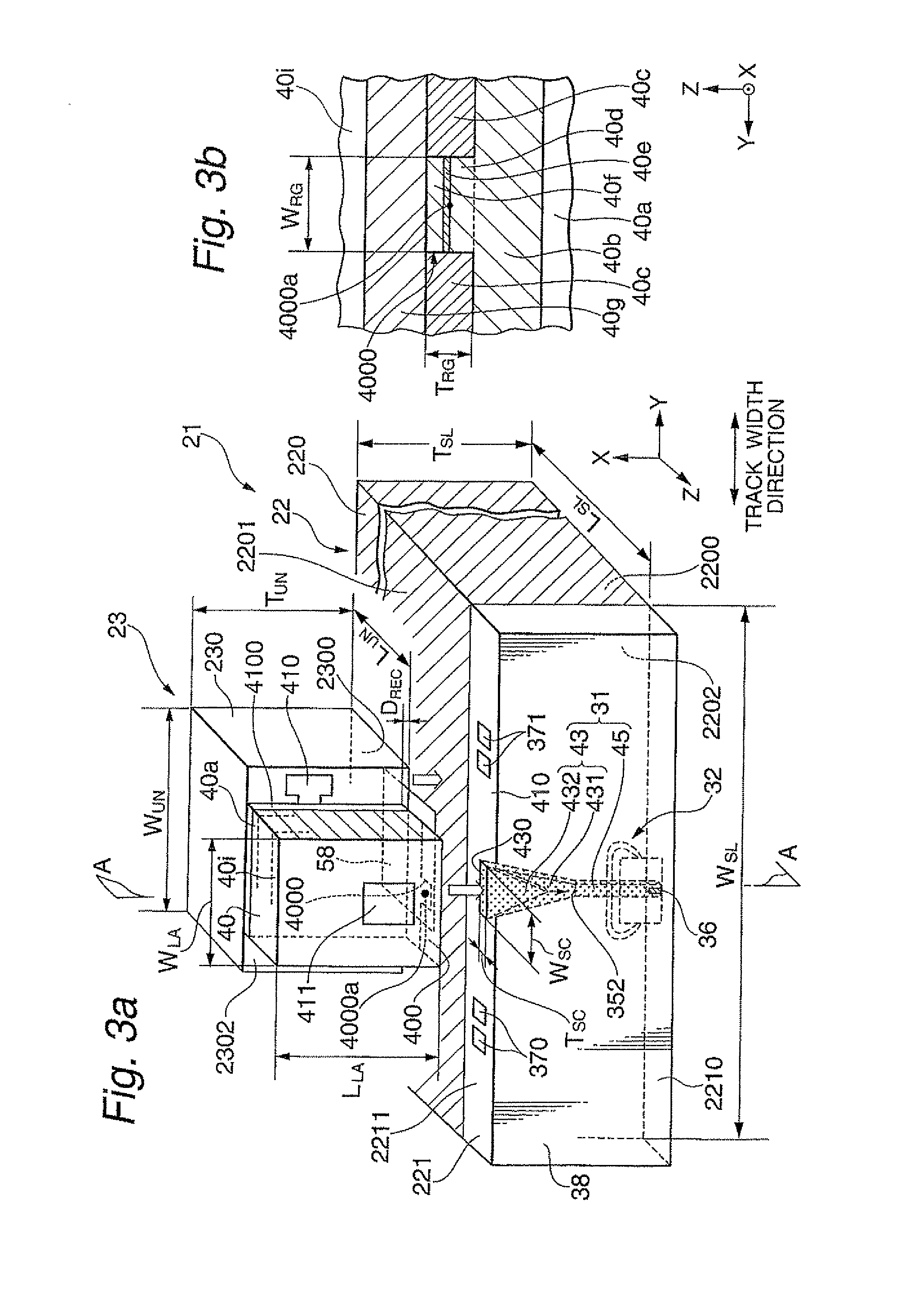
[0048]FIG. 1 shows a perspective view schematically illustrating a structure of a major part in o...


PUM

PropertyMeasurementUnit
thicknessaaaaaaaaaa
melting pointaaaaaaaaaa
angleaaaaaaaaaa

Abstract

Provided is a method for manufacturing a thermally-assisted magnetic recording head with “composite slider structure”. In the method, the waveguide is irradiated with a first light from opposed-to-medium surface side, and the passing first light is detected on back surface side to obtain an image of the light-receiving end surface, and a light-receiving center position is determined from the image. Further, the light source is irradiated with a second light from opposite side to joining surface, and the passing second light is detected on the joining surface side to obtain an image of the light-emitting end surface, and a light-emitting center position is determined from the image. Then, the slider and the light source unit are moved based on the determined positions of the light-receiving and light-emitting centers, aligned and bonded. As a result, alignment can be performed with high accuracy in a short process time under simplified process.

Description

BACKGROUND OF THE INVENTION[0001]1. Field of the Invention[0002]The present invention relates to a thermally-assisted magnetic recording head fabricated by joining a slider and a light source unit that includes a light source, and further relates to a method for manufacturing the thermally-assisted magnetic recording head.[0003]2. Description of the Related Art[0004]As the recording densities of magnetic recording apparatuses become higher, as represented by magnetic disk apparatuses, further improvement has been required in the performance of thin-film magnetic heads and magnetic recording media. As the thin-film magnetic heads, a composite-type thin-film magnetic head is widely used, which has a stacked structure of a magnetoresistive (MR) element for reading data and an electromagnetic transducer for writing data.[0005]Whereas, the magnetic recording medium is generally a kind of discontinuous body of magnetic grains gathered together, and each of the magnetic grains has a single...

Claims


Application Information

Patent Timeline
Patent Type & Authority Applications(United States)
IPC IPC(8): G11B5/02G11B5/127
CPCG11B5/314G11B5/6088Y10T29/49032G11B2005/0021G11B5/105G11B2005/001
Inventor MORI, NOBUYUKITAKAYAMA, SEIICHITSUCHIYA, YOSHIHIROITO, YASUHIROSHIMAZAWA, KOJI
Owner TDK CORPARATION
Why Eureka
Try Eureka