Method and apparatus for manufacturing a rotor

a manufacturing method and a technology for rotors, applied in electrical equipment, climate sustainability, shaping tools, etc., can solve the problems of time-consuming and expensive steps of the manufacturing process, and achieve the effects of preventing residual stress, increasing yield strength and hardness of plate materials, and large deformation

Active Publication Date: 2011-10-13
SIEMENS GAMESA RENEWABLE ENERGY AS
View PDF2 Cites 3 Cited by
  • Summary
  • Abstract
  • Description
  • Claims
  • Application Information

AI Technical Summary

Benefits of technology

[0014]Another advantage of the present invention is that it does not remove rotor material from the rotor during the manufacturing process as opposed to the known methods using machining, for example by using a turning machine.
[0015]As already mentioned, the forming process can in some embodiments of the invention be performed as cold forming The metal cylinder, in particular the steel cylinder, is deformed at a temperature substantially below the recrystallization point of the material, for example at room temperature. Cold forming increases the yield strength and hardness of the plate material by introducing defects into the material's crystal structure, resulting in hardening.
[0016]In another embodiment, the fowling process can be performed as a hot forming process. The metal cylinder, in particular the steel cylinder, is in this case heated above its recrystallization point and the deformed. Hot forming allows large deformations to be achieved and prevents residual stress from accumulating in the material, which ensures good dimensional stability. For example, temperatures of about 600 to 700 degrees Celsius can be used.
[0017]As already mentioned above, the first step of the method comprises providing a hollow metal cylinder, in particular a hollow steel cylinder. The cylinder should have a suitable wall thickness, for example in the range of 35 mm to 55 mm, and the length / height of the cylinder should be substantially the length / height of the desired finished rotor, in particular rotor yoke. The cylinder can be made from any suitable metal, in particular iron, or metal alloy, in particular any suitable steel alloy.
[0018]In a preferred embodiment, a pressing means is arranged inside or around the cylinder, applying a pressing force to at least a part of the inner or outer surface of the cylinder. In such an embodiment, the cylinder can be provided having a diameter slightly smaller than the desired final diameter of the rotor. The pressing means can now apply a sufficient force to one or more areas of the cylinder, so that the desired inner diameter is achieved. Preferably, a pressing force in a radial direction of the cylinder is applied. In any case, the force generated by the pressing means must be sufficient to allow the cylinder material to reach a plastic deformation state.
[0019]In an advantageous embodiment, the surface of the pressing means contacting the cylinder is structured such that the contacted surface of the cylinder takes a predetermined texture. In this manner, the inner or outer surface of the cylinder can be structured while the pressing is in progress. The pressing means can be designed to allow the forming of inner or outer surfaces of the rotor of various textures. For example, if a rotor yoke or the like is to be manufactured, the texture made may have, in a cross-sectional view, the form of a polygon composed of a finite sequence of straight line segments. The number of these segments can correspond to the number of pole magnets to be mounted to the rotor subsequently.

Problems solved by technology

These processing steps are time consuming and expensive steps of the manufacturing process.

Method used


Image

  • Method and apparatus for manufacturing a rotor
  • Method and apparatus for manufacturing a rotor
  • Method and apparatus for manufacturing a rotor

Examples


Embodiment Construction

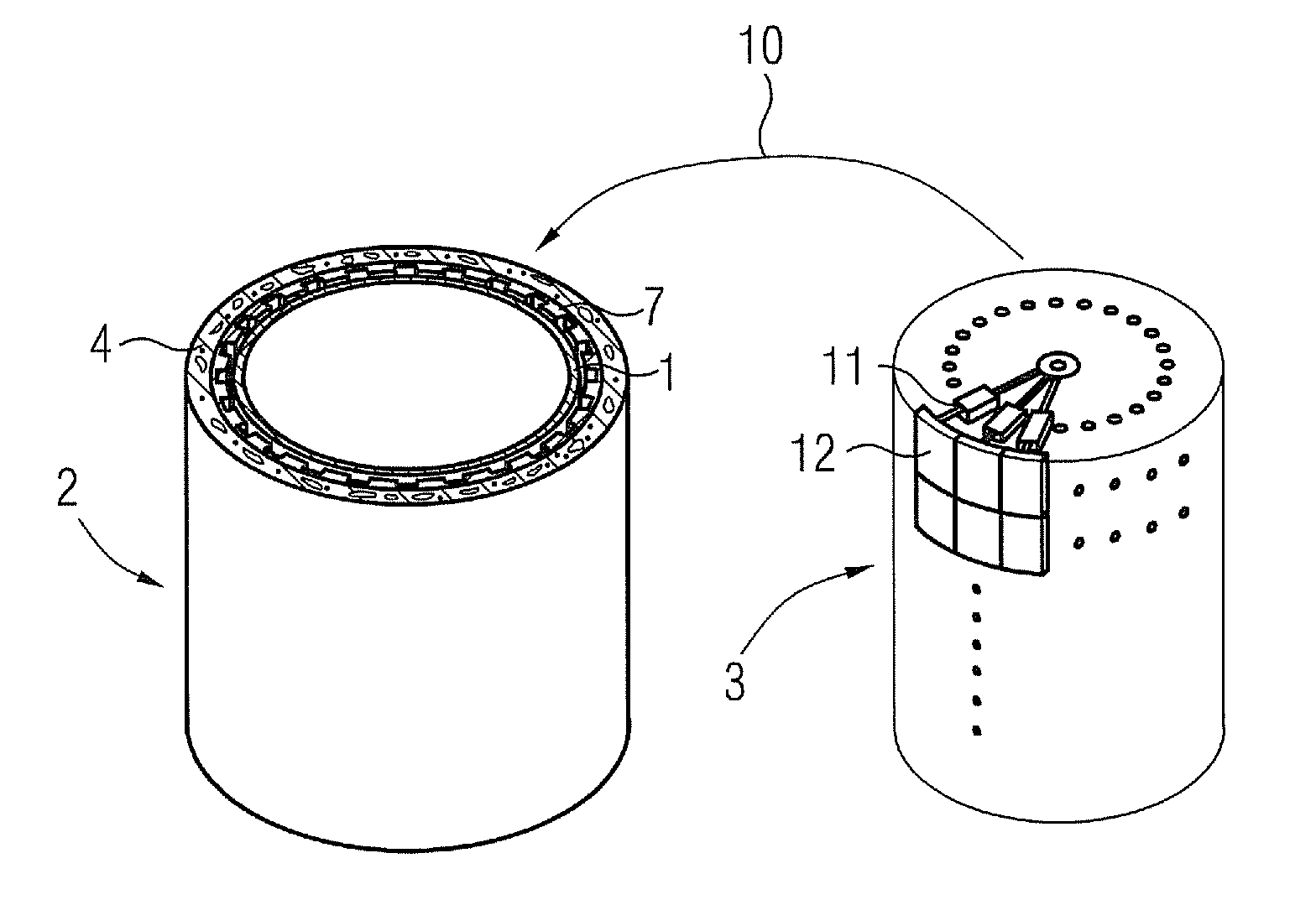
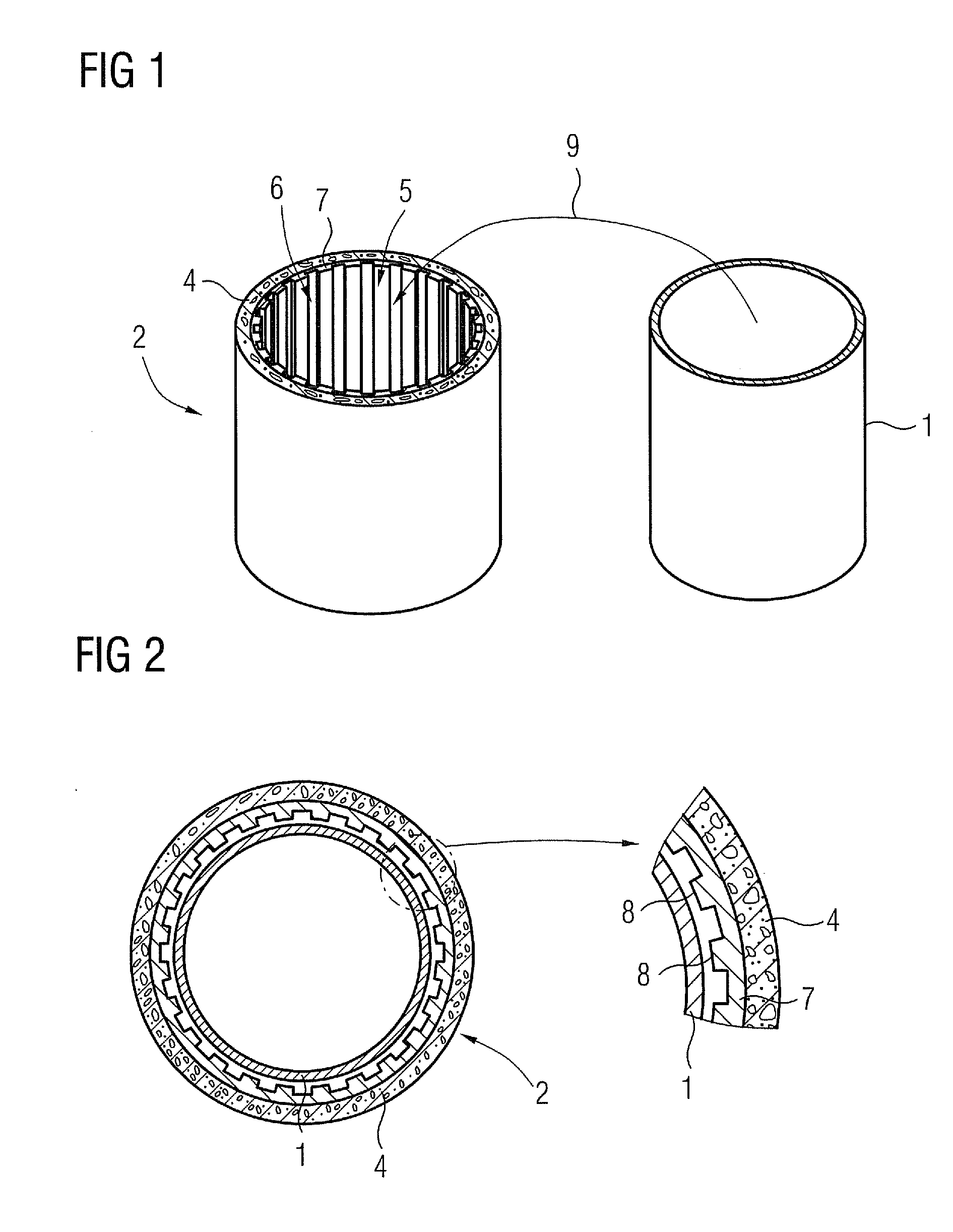
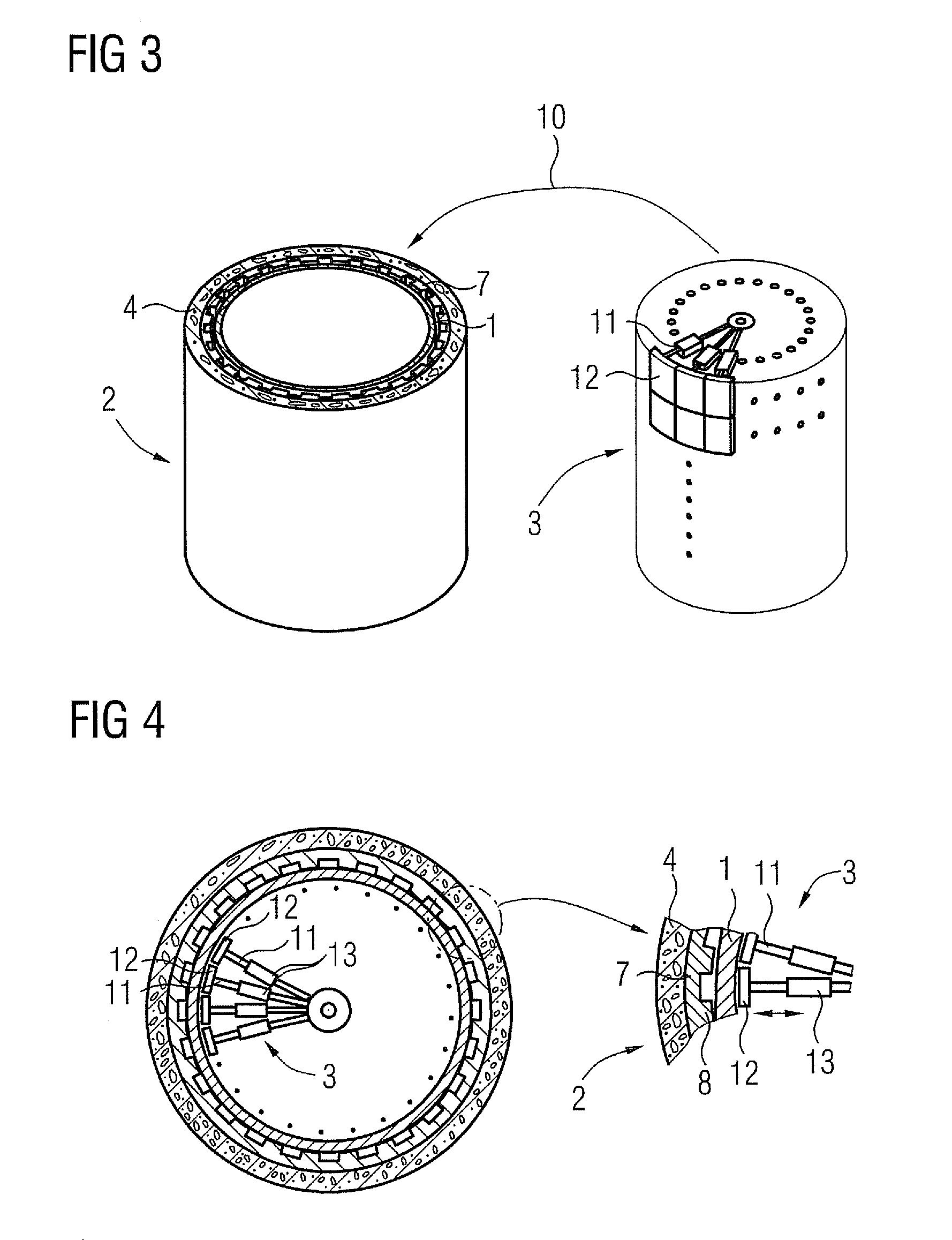
[0039]As a first step of the inventive method for both embodiments discussed here, a hollow cylinder 1 is provided, in this case, wherein a rotor yoke for a wind turbine (“rotor” in the following) is to be manufactured, a rolled hollow cylinder 1 made of a suitable steel alloy or iron is used, which can be manufactured using processes known in the art. The cylinder 1 has a wall thickness of 40 mm and a diameter of 4 meters. The inner diameter of the cylinder 1 is slightly smaller than the desired inner diameter, and the length / height of the cylinder 5 is already equal to the desired length / height of the rotor.

[0040]In the first embodiment, the used apparatus comprises a mould element 2 and a pressing means 3. The mould element comprises a layer 4 of armoured concrete defining a cavity 5. The inner surface of the concrete layer has a matrix structure 6, in this case defined by a replaceable matrix structure insert 7. The matrix structure is chosen to correspond to a desired predeterm...


PUM

PropertyMeasurementUnit
temperatureaaaaaaaaaa
diameteraaaaaaaaaa
diameteraaaaaaaaaa

Abstract

A method and apparatus for manufacturing a rotor are provided. The rotor is particular a rotor yoke for a wind turbine generator. A hollow rolled metal cylinder is provided and plastically deformed permanently to a predetermined shape and a predetermined size. The apparatus includes a pressing unit and a mould element.

Description

CROSS REFERENCE TO RELATED APPLICATIONS[0001]This application claims priority of European Patent Office Application No. 10159375.4 EP filed Apr. 8, 2010, which is incorporated by reference herein in its entirety.FIELD OF INVENTION[0002]The invention concerns a method and an apparatus for manufacturing a rotor for an electrical machine, in particular a rotor yoke for a wind turbine generator.BACKGROUND OF INVENTION[0003]Hollow shafts of a large diameter, for example, a diameter of more than one meter, are needed as rotors for some special applications. An example for such an application is a wind turbine, where such a hollow shaft is usually used as a rotor yoke for a wind turbine generator, for example a direct drive wind turbine generator.[0004]Such a rotor yoke of a generator for a large scale modern wind turbine can be built up of a cylinder of rolled steel, having a steel thickness of about 40 mm and a diameter of for example, four meters for an outer rotor type generator. Rotor...

Claims


Application Information

Patent Timeline
Patent Type & Authority Applications(United States)
IPC IPC(8): H02K15/02B21D51/16
CPCB21D51/10B21J13/02Y02E10/722B21D39/08B21K23/00Y02E10/721B21C37/202B21C37/0803Y10T29/49012F05B2230/26Y02E10/725B21J5/04H02K7/1838B21K5/20Y10T29/49009F03D11/00B21J5/12H02K15/03F03D1/06Y10T29/49805Y02E10/72Y02P70/50H02K15/02H02K1/22
Inventor ANDERSEN, KURTSTIESDAL, HENRIK
Owner SIEMENS GAMESA RENEWABLE ENERGY AS
Why Eureka
Try Eureka