Furnace Vent with Water-Permeable Inner Pipe

a technology of water-permeable inner pipes and furnace vents, which is applied in the direction of fluid heaters, combustion processes, lighting and heating apparatus, etc., can solve the problems of increasing manufacturing and maintenance costs of the furnace system, affecting the efficiency of the furnace, and the construction of the membrane module is relatively complicated

Inactive Publication Date: 2011-10-13
CARRIER CORP
View PDF11 Cites 13 Cited by
  • Summary
  • Abstract
  • Description
  • Claims
  • Application Information

AI Technical Summary

Benefits of technology

[0011]In yet another aspect of this disclosure, a method of improving efficiency of a furnace having a burner unit in operative connection with a heat exchanger unit is disclosed. The method may include the steps of feeding ambient air into the burner unit through an intake pipe, discharging flue gas from the heat exchanger through an exhaust pipe having a longitudinal section longitudinally disposed within the intake pipe, and allowing water or water vapor in the flue gas to permeate through the at least one longitudinal section of the exhaust pipe.

Problems solved by technology

However, the construction of the membrane module is relatively complicated and requires, for example, an array of parallel exhaust tubes made of a hydrophobic polymeric material and orthogonally disposed in the flow path of the intake air.
As a result, the heat and / or moisture exchange capacities of the membrane module are limited.
Moreover, the membrane module requires circulation of a moisture absorbent, such as a hygroscopic liquid like ethylene glycol, which not only increases manufacturing and maintenance costs of the furnace system but may also cause undesirable noises as the flowing intake air and / or flue gas interacts with the hygroscopic liquid.
Further, there is a need for a furnace vent with simple construction and low maintenance (i.e. no complex membrane module design or hygroscopic agent).

Method used


Image

  • Furnace Vent with Water-Permeable Inner Pipe
  • Furnace Vent with Water-Permeable Inner Pipe
  • Furnace Vent with Water-Permeable Inner Pipe

Examples


Embodiment Construction

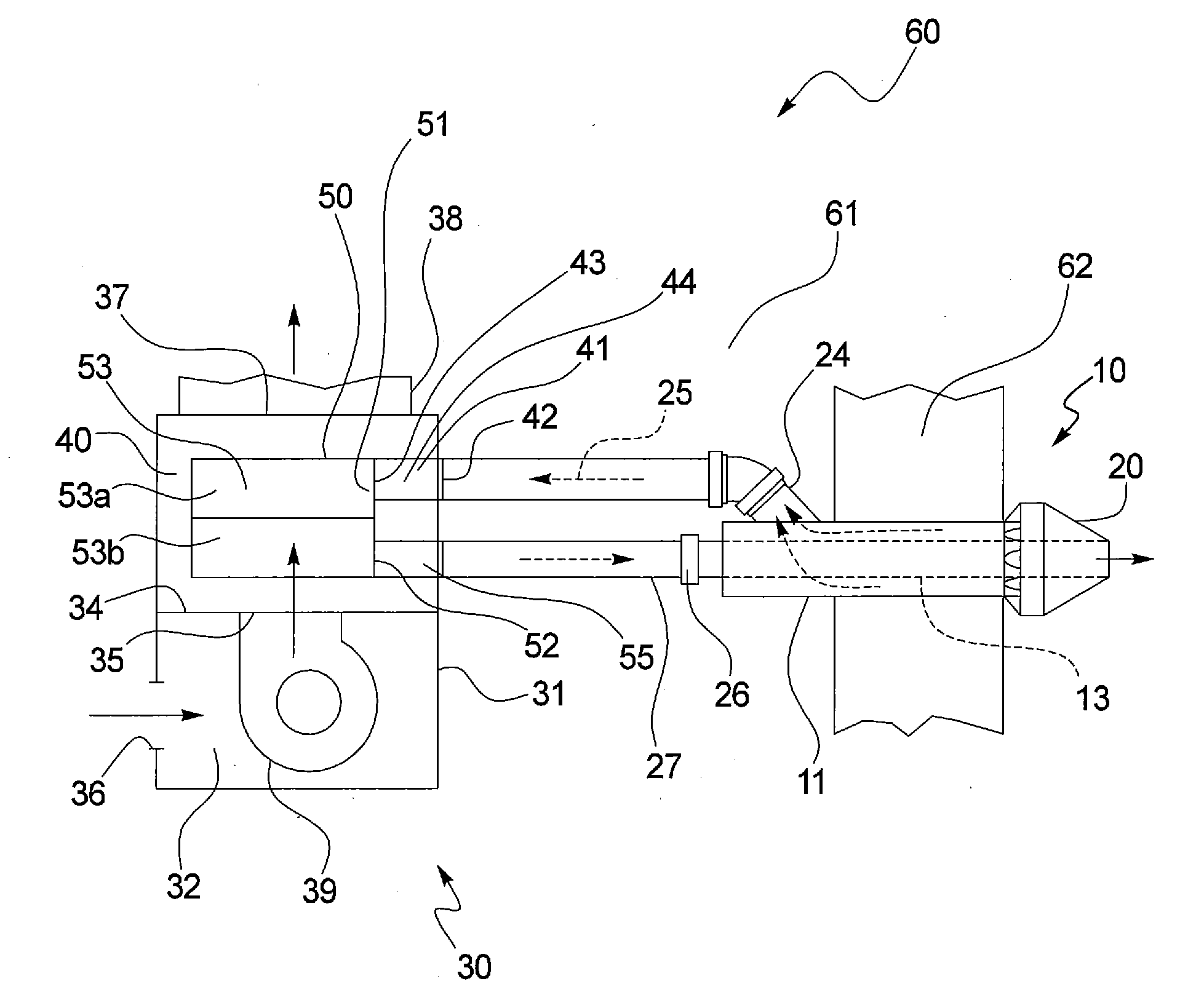
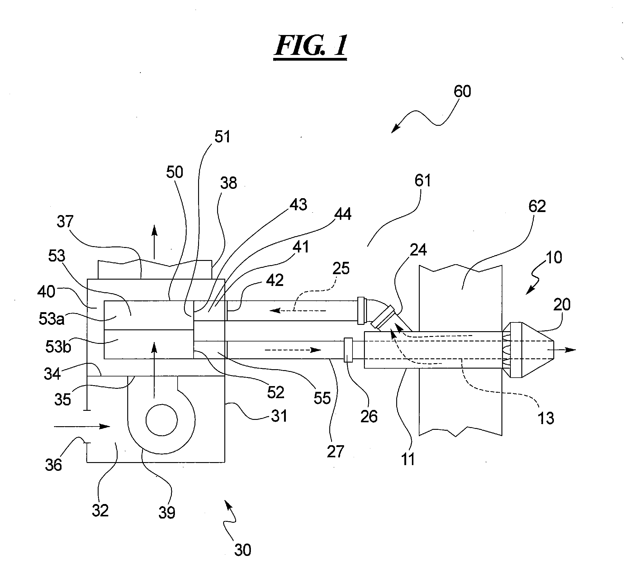
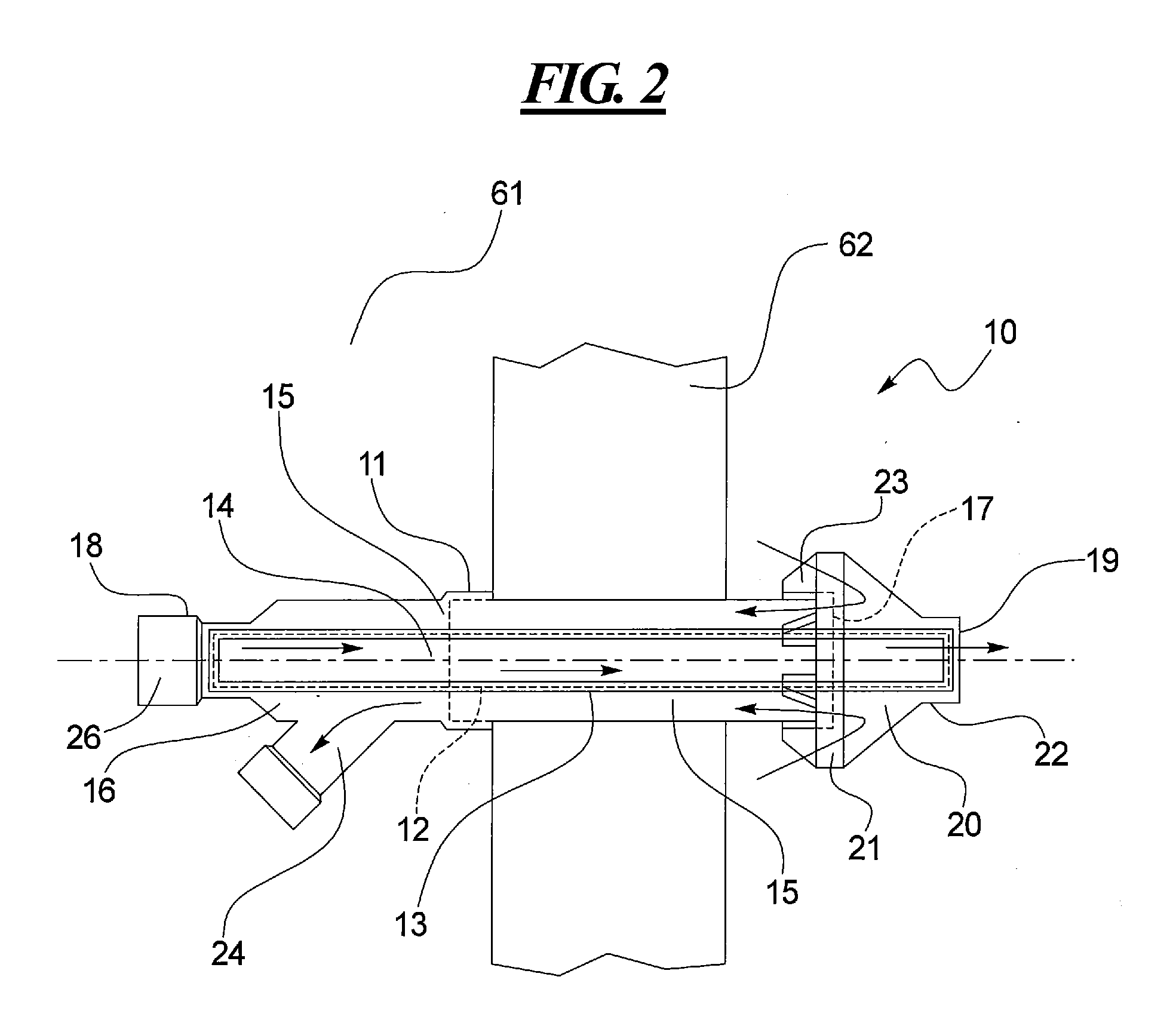
[0018]Referring now to FIG. 1, an exemplary embodiment of an improved vent system generally referred to by reference numeral 10 is schematically illustrated. As disclosed herein, the vent system 10 may be use in conjunction with a combustion device, such as a fuel-fired induced draft furnace 30. However, the combustion device may also be a boiler, water heater, or other suitable fuel-combusting space or water heating device. Furnace 30 may be located in a commercial or residential building 60 having an enclosed interior space 61 separated from air outside of the building 60 through a wall 62.

[0019]In this disclosure, “intake air” refers to outside air that is drawn into the furnace 30 through the vent system 10 before it is combusted. “Flue gas” refers to the combustion exhaust gas produced by the furnace 30. The composition of the flue gas generally depends on the type of fuel combusted, but usually consists of mostly nitrogen (typically more than two-thirds) derived from the combu...


PUM


Abstract

A vent system for improving the efficiency and / or reducing emissions of a combustion device is disclosed. The vent system may include an outer pipe and an inner pipe having a longitudinal section that is permeable to water or water vapor and is longitudinally disposed within the outer pipe. The inner pipe defines a first passageway and the outer and inner pipes define a second passageway therebetween. As the moisture and / or heat are transferred from the flue gas to the intake air through the longitudinal section of the inner pipe, the efficiency of the furnace may be improved and the NOx emission of the furnace may be reduced.

Description

CROSS-REFERENCE TO RELATED APPLICATIONS[0001]This is a non-provisional U.S. patent application, which claims priority under 35 U.S.C. §119(e) to U.S. Provisional Patent Application Ser. No. 61 / 322,554 filed on Apr. 9, 2010, the entirety of which is incorporated by reference herein.TECHNICAL FIELD OF THE DISCLOSURE[0002]This disclosure generally relates to a method and apparatus for improving the efficiency and / or reducing emissions of a furnace and more particularly relates to the use of a furnace vent system with a water permeable and / or heat conductive inner pipe disposed within an outer pipe to pre-moisten and / or pre-heat intake air before it is fed into a burner.BACKGROUND OF THE DISCLOSURE[0003]Combustion devices based on hydrocarbon fuels are widely used to provide thermal, mechanical or electric energies. For example, fireplaces, ovens, furnaces, and boilers have been installed and used in commercial and residential buildings to provide heat, hot water, and other conveniences...

Claims


Application Information

Patent Timeline
Patent Type & Authority Applications(United States)
IPC IPC(8): F24H3/00F24H9/00
CPCF24H3/025F24D2220/06F24H9/0084F23L17/04
Inventor DEMPSEY, DANIEL J.BROWN, MICHAEL L.
Owner CARRIER CORP
Why Eureka
Try Eureka