
Method and Apparatus for Increasing Well Productivity

a well productivity and well technology, applied in the direction of earthwork drilling tools, directional drilling, borehole/well accessories, etc., can solve the problems of reducing the jet energy of ambient hydrostatic pressure, reducing the depth of the slot to less than a meter, and reducing the depth of the slot quickly,

Inactive Publication Date: 2011-10-13
CARTER JR ERNEST E
View PDF12 Cites 57 Cited by
  • Summary
  • Abstract
  • Description
  • Claims
  • Application Information

AI Technical Summary

Benefits of technology

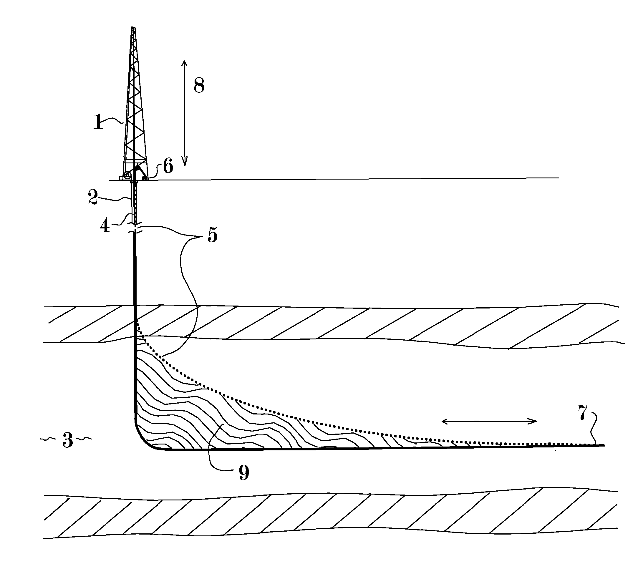
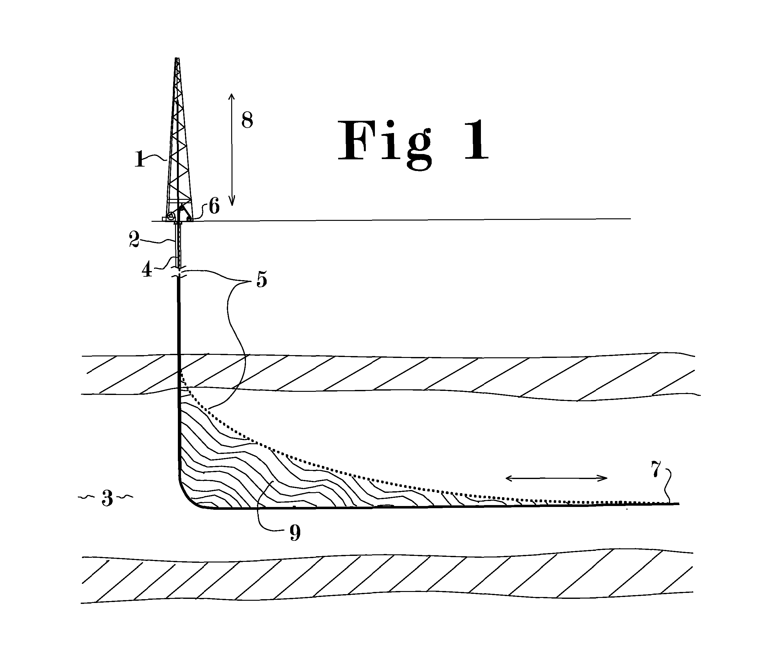
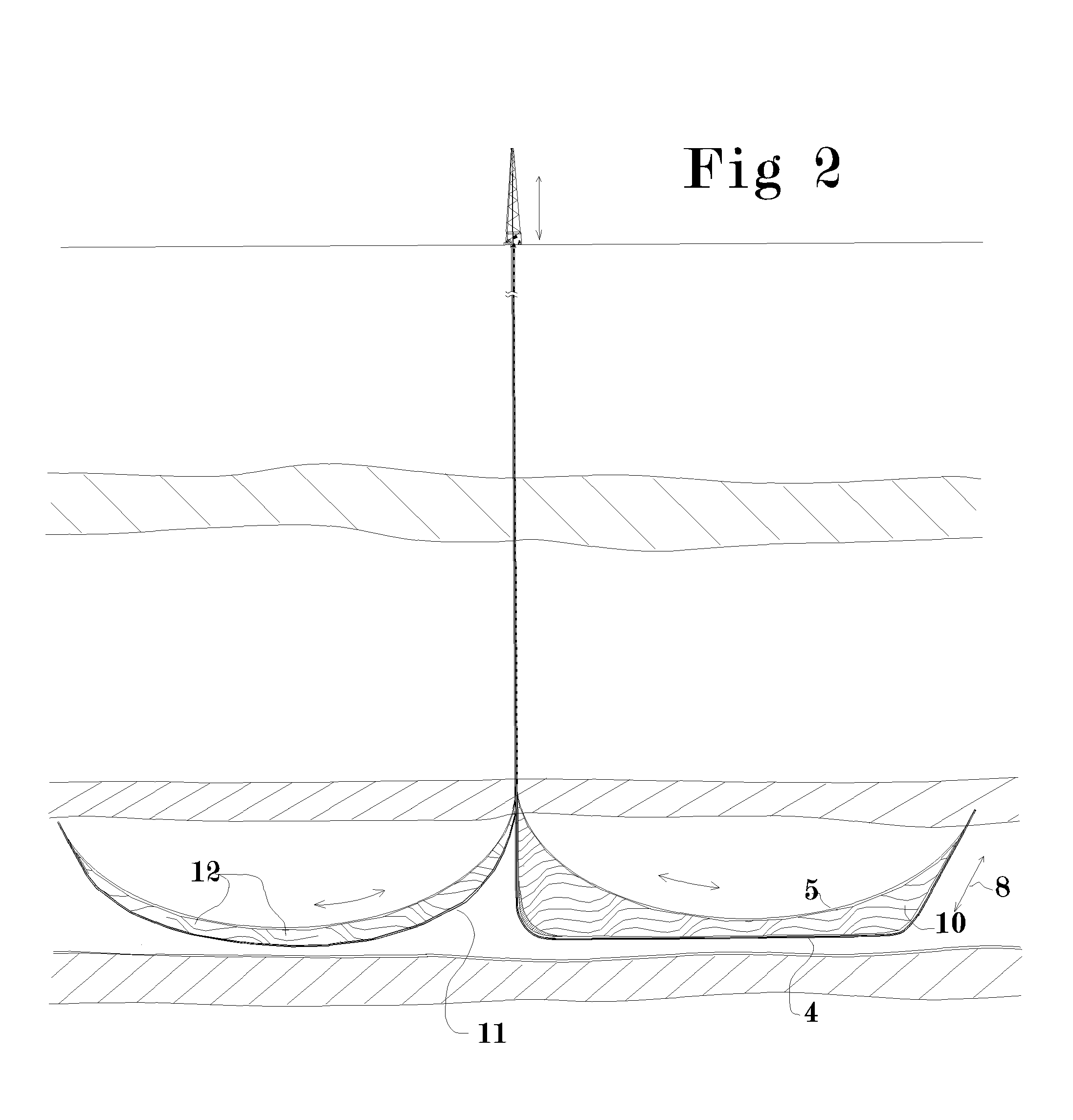
[0006]The present patent application describes a method and apparatus for increasing well productivity without hydro-fracturing. The method describes a method and apparatus for manipulating an abrasive cutting member within a well to cut an extended slot. This extended slot connects the well to a substantial cross sectional area of a desired producing formation whereby the rate of flow of resources between the formation and the well is substantially increased. The effective increase in surface area may provide results comparable to hydraulic fracturing while avoiding the environmental issues associated with that technology. The method and apparatus described herein provide means of enhancing a well by mechanical cutting of a very extensive planar groove, herein referred to as a slot, cut, gallery, or panel, along a well bore and extending away from the well bore axis and cutting across a very large cross section of the formation.
[0008]The slot may be thinner than the diameter of the well bore but is much thicker and more uniform than a man-made hydraulic fracture and preferably may extend a hundred feet or more into the formation all along a substantial length of the well bore connecting it to a substantial cross sectional area of the desired producing formation. The “desired producing formation” may contain oil, natural gas, soluble mineral resources, geothermal heat, Kerogen (oil shale) or any resource. The slot acts as a gathering gallery that contacts a very large surface area potentially crossing many existing fractures in the formation. Many of these natural fractures also expose a large surface area of the formation. This increases the potential flow rate between the formation and the well bore much like freeways increase the mobility of cars within a city. The slot can also facilitate flow of material from the well into the formation. This could be used to inject carbon dioxide into a formation at lower pressure so that it remains in a well defined area. In this case the resource is a disposal zone. The slot can also be used as a down hole heat exchanger to harvest geothermal heat.

Problems solved by technology

However the jet energy is reduced by ambient hydrostatic pressure and also diminishes rapidly away from the jet orifice, especially in a liquid environment, effectively limiting the depth of a slot to less than a meter.
Jet nozzles on the end of a flexible hose have been shown to be capable of carving out cavities around a well bore as in U.S. Pat. No. 3,958,641 but are unsuitable for cutting deep slots because they cut randomly in all directions and not just in a planar path.
Under-reaming tools have mechanisms that expand down hole and enlarge the well bore itself but are limited to doubling or tripling the bore diameter.
Mechanical tools that drag along the bore hole or have rotating end mill style cutters can cut a shallow groove but generally can not form cuts deeper than the diameter of the well bore and none in prior art can cut a slot deeper than twice the diameter of the wellbore.
Generating the required mechanical force to cut rock deep in a slot away from a relatively small borehole becomes increasingly difficult as the cut deepens.
This approach would form a cut that is very tall vertically compared to its horizontal length and may be less desirable to access a thin gas production formation.
Drilling a “U” shaped hole down and back to the surface is difficult and making two independently drilled holes connect to form a “U” is also difficult.
Another problem is that for holes that traverse nearly 180 degrees of arc, the friction may be so great that the cable becomes stuck.
Placing pulley sheaves down hole on the ends of pipes can reduce friction but the required pulley diameter is generally too large to place in the common size of hole.
This method is also thought to have feasibility issues related to friction of the wire saw around too great of a total arc of contact, nearly 180 degrees at the intersection plus the total arc of curvature of both wells.
Since friction increases exponentially with the contact angle the cable would be likely to be stuck by friction alone.
These have been considered for cutting a slot in a wellbore but they are limited by the minimum diameter of the wheel supporting and driving the cutting elements of the cable or chain.
The ratio of the bore diameter to the width and depth of the cut that is mechanically feasible is believed insufficient for increasing the productivity of wells.
Delivering a sufficient amount of energy to the device to cut at a reasonable rate is also problematic.
This type of mechanism cutting more than two or three times the borehole diameter into the wall of the hole for a substantial length is probably not possible.
During drilling of wells the reduced diameter body of a drill pipe can become pressed against the wall of the hole at a bend or angle change and if the wall of the hole is soft the moving pipe may accidently cut a slot into the wall.
This slot is known as a keyseat and is highly undesirable since the larger diameter drill pipe joints and drill bit can not be pulled back up through this keyseat.
While many efforts have been made to prevent the cutting of a keyseat or to recover from one, no prior art has contemplated the potential benefit of intentionally cutting a keyseat.

Method used


Image

  • Method and Apparatus for Increasing Well Productivity
  • Method and Apparatus for Increasing Well Productivity
  • Method and Apparatus for Increasing Well Productivity

Examples


application embodiment

DETAILED DESCRIPTION OF GEOTHERMAL APPLICATION EMBODIMENT

[0095]Natural geothermal reservoirs where heat is very near the earth's surface produce hot water that can be used as an energy source for electrical generation. Suitable geologic conditions for natural shallow geothermal reservoirs are rare but at greater depths heat is available over most of the planet. However daunting technical problems have limited the utilization of this heat resource.

[0096]Artificial fracture systems tend to allow for a preferential flow that mines heat from a much smaller area than intended so they tend to cool after a few years. Waters present in the geothermal formation are often corrosive and tend to deposit mineral scale on equipment they come in contact with. High temperatures of up to 300 Celsius greatly limit the types of equipment that can survive in a geothermal well. Rock in geothermal areas is often very hard and has many dry fissures that can interfere with conventional drilling and complet...


PUM


Abstract

This patent application discloses method and apparatus to cut an extended slot connecting a well to a substantial cross section of a desired producing formation whereby material can flow freely between the formation and the wellbore and at least partially overcome the flow limitations of low permeability formations without the environmental issues associated with hydraulic fracturing. It is further disclosed that the connection between said slot and the formation may be further enhanced by explosive or combustive processes that rapidly generate gas pressure within the large surface area of the slot, thereby changing its characteristics and forcing open additional fractures into the cross section of formation exposed to the slot. The method may significantly increase the recoverable percentage of natural gas from low permeability deposits such as shale and coal.

Description

CROSS-REFERENCE TO RELATED APPLICATIONS[0001]This PCT patent application claims benefit of two previous provisional patent applications PPA No. 61 / 201,400 filed Dec. 10, 2008 and provisional patent application No. 61 / 217,941 filed Jun. 5, 2009, both by the present inventor, which are incorporated by reference.FEDERALLY SPONSORED RESEARCH[0002]At least a portion of this invention was made under a government contract DE-AC26-07NT42677 subcontract 07122-07 awarded to Carter Technologies Co, a Texas Corporation and small business wholly owned by the inventor Ernest E. Carter, Jr. Carter has applied for and received notice of patent waver under P.L.96-517 (FAR 52.227-12 patent rights—Waiver (July 1996), as modified by 10 CFR 784, DOE Patent Waiver Regulations) and Carter has elected title to this invention and all patent applications arising from the work.BACKGROUNDField of the Invention[0003]A well is typically drilled in order to extract resources from the earth or as a zone to dispose...

Claims


Application Information

Patent Timeline
Patent Type & Authority Applications(United States)
IPC IPC(8): E21B43/11
CPCE21B43/26E21B11/06E21B43/305E21B7/04E21B7/28E21B43/04E21B43/263
Inventor CARTER, JR., ERNEST E.
Owner CARTER JR ERNEST E
Learn More