
Submersible hydraulic artificial lift systems and methods of operating same

Inactive Publication Date: 2011-10-13
SMITH DAVID RANDOLPH +1
View PDF9 Cites 23 Cited by
  • Summary
  • Abstract
  • Description
  • Claims
  • Application Information

AI Technical Summary

Benefits of technology

[0016]To meet the needs discussed above and address the disadvantages of conventional systems, the present disclosure provides a submersible hydraulic lift system comprising a first submersible pump assembly and a first submersible hydraulic engine component connected to a first submersible hydraulic transducer component. At least a portion of said first submersible pump assembly is located below the surface. Further, at least a portion of said first submersible hydraulic engine is located below the surface. The first submersible hydraulic transduce

Problems solved by technology

When a fluid, such as oil and natural gas, is being produced from a subterranean reservoir, the reservoir may not have sufficient energy, or the reservoir strata may have insufficient fluid conductivity, to eject fluids to the surface at a commercial fluid flow rates.
This benefit, however, is typically only temporary because fluid production to the surface will usually decline as fluids are extracted from the reservoir.
As mentioned above, increased fluid production from a hydraulically fractured well having a velocity string is not maintained indefinitely.
Instead, as the reservoir pressure continues to be depleted during fluid extraction, the fluid velocity in the coaxially inserted velocity string becomes insufficient to lift the well fluids to the surface at a commercial production rate.
While, additional smaller velocity strings can be coaxially inserted to increase fluid velocity, this method has its drawbacks.
Further, inserting additional velocity strings does not address the decreasing reservoir energy as a reservoir is depleted of fluids, where the reservoir energy continues to decrease until it is insufficient to lift fluids to the surface at commercial rates.
Moreover, inserting additional velocity strings is inconvenient and not commercially expedient because to use the well configuration that was lastly deployed rather than extracting the final well configuration with an expensive rig intervention only to deploy some other configuration for further extracting well fluids at the current conditions.
As such, these known artificial lift methods may not be best suited for extracting fluids from gas wells.
An example of such pumps is disclosed in U.S. Pat. No. 2,081,221 to Clarence J. Coberly. These conventional systems of hydraulically lifting fluids from oil and gas wells introduce significant environmental hazards because they place high pressure hydraulic positive displacement piston pump systems at the surface.
It is further known to those familiar with producing oil and gas wells with hydraulic pumping systems that the use of water as a power fluid is limited in cold climates.
This has many disadvantages, including extra energy use and the possibility of introducing hazardous chemicals into the environment.
The field of dewatering gas wells or as it is often known in the oil and gas industry as artificial lifting gas wells, is reluctant to adopt the current methods of hydraulic powered submersible hydraulic motors, engines, compressors, and pumps as most are currently powered by surface positive displacement piston pump systems.
These conventional art uses of surface located positive displacement systems are dangerous and often outlawed by city ordinances for many reasons.
In particular, there are likely risks associated with these systems, such as over pressurization of the surface equipment when a well hydraulic fluid system plugs, or a surface valve closes on the positive displacement tri-plex pumps discharge side, which causes a high pressure release of hydraulic power fluid.
Further, the conventional positive displacement pumps placed at the surface have large dimensions that cannot easily be accommodated in a well conduit and hence are located on the surface of the earth or at best on small skids with fluid containments beneath them.
This configuration also introduces risks both at the surface environment and into a hydraulic power system, as an inadvertent closure of a valve, or the plugging of a valve, can cause a rapid pressure rise in the positive displacement pumps discharge often resulting in a catastrophic rupture and leak of the hydraulic power system.
This catastrophic pressure rupture causes oil spills, fires, pollution, and danger to humans.
Additionally, the conventional hydraulic power pumps surface arrangements have packing, and oil lubricants in their power ends that can leak and spill oil on the earth's surface.
Hence the conventional hydraulic pumping system for lifting fluids from wells have many drawbacks including continual and frequent oil changes, and pump maintenance further introducing the opportunity to have an oil spill at the surface.
Additional drawbacks include a large surface footprint, which makes the conventional systems difficult to house or encapsulate to contain leaks from the pump system.

Method used


Image

  • Submersible hydraulic artificial lift systems and methods of operating same
  • Submersible hydraulic artificial lift systems and methods of operating same
  • Submersible hydraulic artificial lift systems and methods of operating same

Examples


Embodiment Construction

[0036]As used herein, “a” or “an” means one or more. Unless otherwise indicated, the singular contains the plural and the plural contains the singular. Where the disclosure refers to “perforations” it should be understood to mean “one or more perforations”.

[0037]As used herein, “surface” refers to locations at or above the surface of the earth.

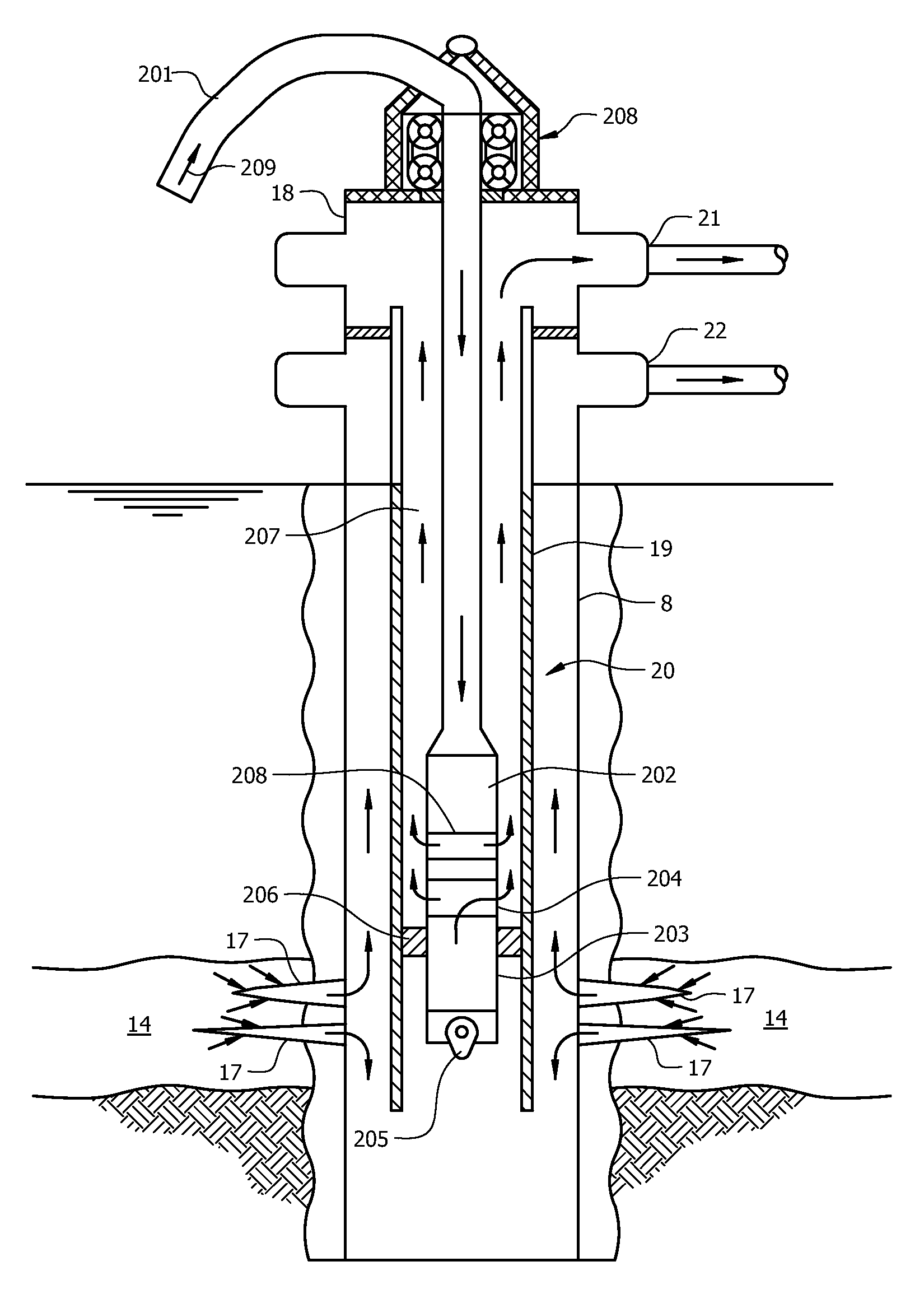
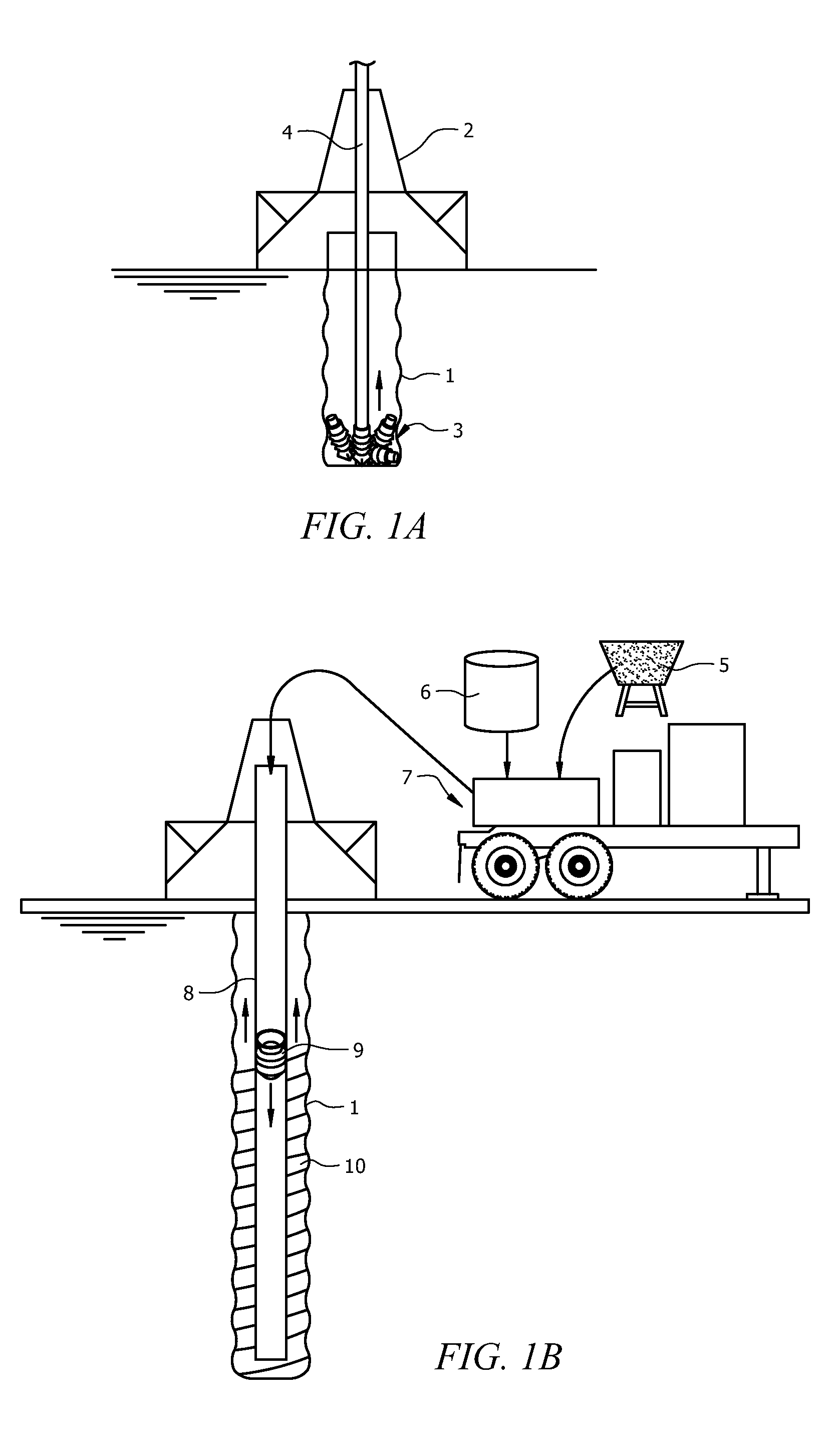
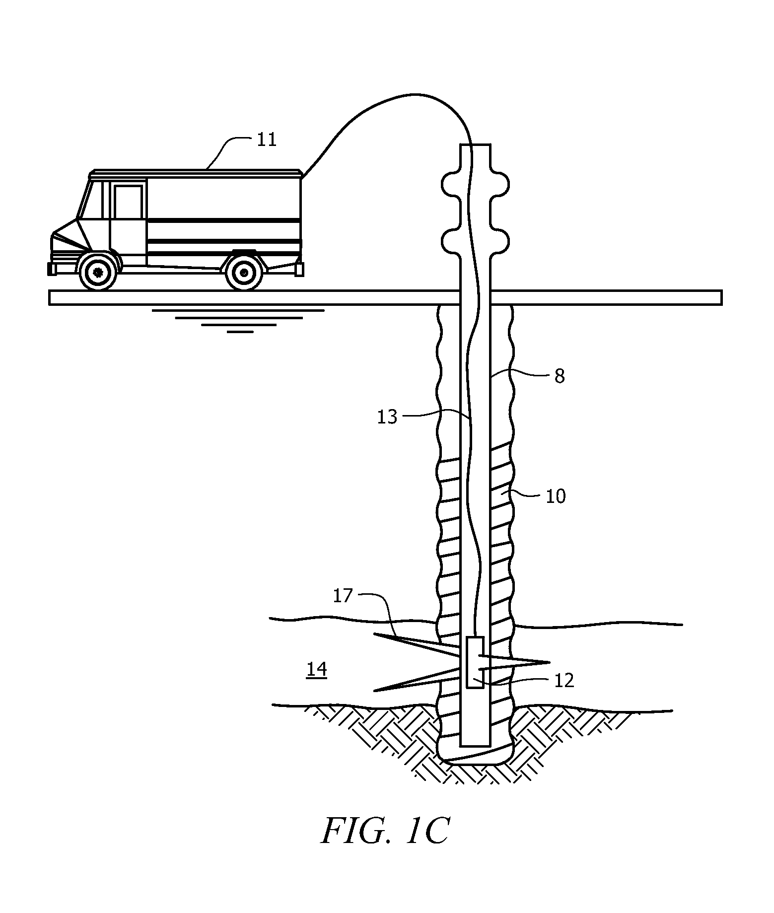
[0038]Referring to FIG. 1, sequential phases of an embodiment of the well construction and production enhancement process of the present disclosure are shown. During the first phase illustrated by FIG. 1A, well bore 1 is drilled using a drilling rig 2, which has a drill pipe 4 attached. Drill pipe 4 has drilling bits 3 attached to its distal end that allows for drilling of well bore 1. After the well bore 1 is drilled to a desired depth and diameter, a casing is placed within the well bore 1. The drilling equipment and method to drill well bore 1 are known to those skilled in the art. Referring to FIG. 1B, the next phase involves the wellbore ...


PUM


Abstract

The present invention is directed to methods for extracting fluids from oil and gas wells. More specifically, it is directed toward methods and apparatuses to power and control down hole hydraulic devices using subterranean centrifugal pumps. This invention represents a vast improvement over current hydraulic artificial lift systems. This invention provides for safe, efficient, and increased fluid recovery of oil and gas reserves from subterranean reservoirs in all types of wells, including deviated and horizontal wells.

Description

CROSS-REFERENCE TO RELATED APPLICATIONS[0001]The present application claims priority to U.S. Application No. 61 / 321,605, which was filed on Apr. 7, 2010, entitled METHOD AND APPARATUS TO OPERATE AND CONTROL SUBMERSIBLE HYDRAULIC MOTORS, the disclosure of which is incorporated by reference.TECHNICAL FIELD[0002]The present disclosure is directed to methods and apparatus to extract fluids from subterranean reservoirs, particularly oil and gas reservoirs. More specifically, this disclosure provides methods and apparatuses to increase the recovery of fluid reserves, such as oil and gas, from subterranean reservoirs using an improved hydraulic system to power subterranean devices.BACKGROUND OF THE INVENTION[0003]When a fluid, such as oil and natural gas, is being produced from a subterranean reservoir, the reservoir may not have sufficient energy, or the reservoir strata may have insufficient fluid conductivity, to eject fluids to the surface at a commercial fluid flow rates. A convention...

Claims


Application Information

Patent Timeline
IPC IPC(8): E21B43/00
CPCE21B43/129E21B43/34F04B47/10E21B47/18F04B47/04E21B47/0007E21B47/008
Inventor SMITH, DAVID RANDOLPHVENTURA, MARK CHRISTOPHER
Owner SMITH DAVID RANDOLPH
Learn More