Brake System for a Motor Vehicle and Method for Controlling said Brake System

Inactive Publication Date: 2011-10-13
ROBERT BOSCH GMBH
View PDF8 Cites 12 Cited by
  • Summary
  • Abstract
  • Description
  • Claims
  • Application Information

AI Technical Summary

Benefits of technology

[0005]The brake system according to the invention having the features of claim 1 has a hydraulic muscle-power-operated or auxiliary-power-operated brake system and a hydraulic externally powered brake system. An auxiliary-power-operated brake system means that the master brake cylinder has a brake booster. A brake booster is, at any rate for simple embodiments of the invention, not absolutely necessary, for which reason a muscle-power-operated brake system is also possible. The externally powered brake system has a hydraulic pressure source which is operated by external power, for example a hydraulic pump, which is driven by an electric motor. The brake system according to the invention is suitable for “blending”, that is to say for compensating the braking effect of an electric drive motor, which is operated as a generator, in a motor vehicle. In particular, the braking effect of the brake system is reduced, and this brakes the vehicle wheels which are driven with the electric drive motor. In this way, the distribution of the braking force between the front axle and the rear axle is not changed by the braking effect of the electric drive motor in the generator mode. A controllable brake booster permits the muscle power which is necessary to activate the brakes to be increased by reducing the boosting by said brake booster. As a result, the customary muscle power for activating the brakes is possible if the braking effect of the brake system is reduced in order to compensate the braking effect of the electric drive motor in the generator mode.

Problems solved by technology

The braking power of the electric drive motor in the generator mode is dependent, inter alia, on the velocity of the vehicle, and braking to a stationary state is not possible with the electric drive motor.
The braking effect of the electric drive motor in the generator mode is also dependent on the charge state of a vehicle battery (actually an accumulator), and when the vehicle battery is fully charged braking with the electric drive motor in the generator mode is not possible.
Even if a clutch pedal is depressed when shifting gear with a non-automatic transmission, the electric drive motor is mechanically separated from the vehicle wheels if said electric drive motor is not assigned to the vehicle wheels, with the result that the braking effect is interrupted.

Method used


Image

  • Brake System for a Motor Vehicle and Method for Controlling said Brake System
  • Brake System for a Motor Vehicle and Method for Controlling said Brake System

Examples


Embodiment Construction

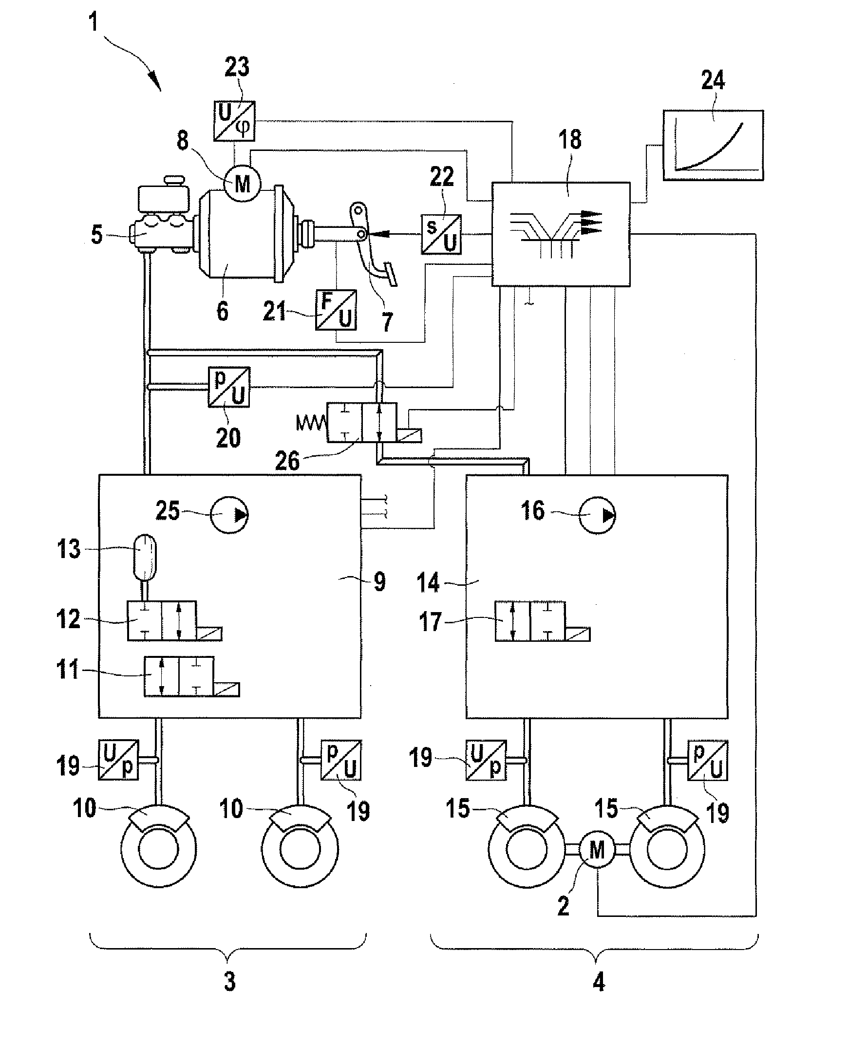
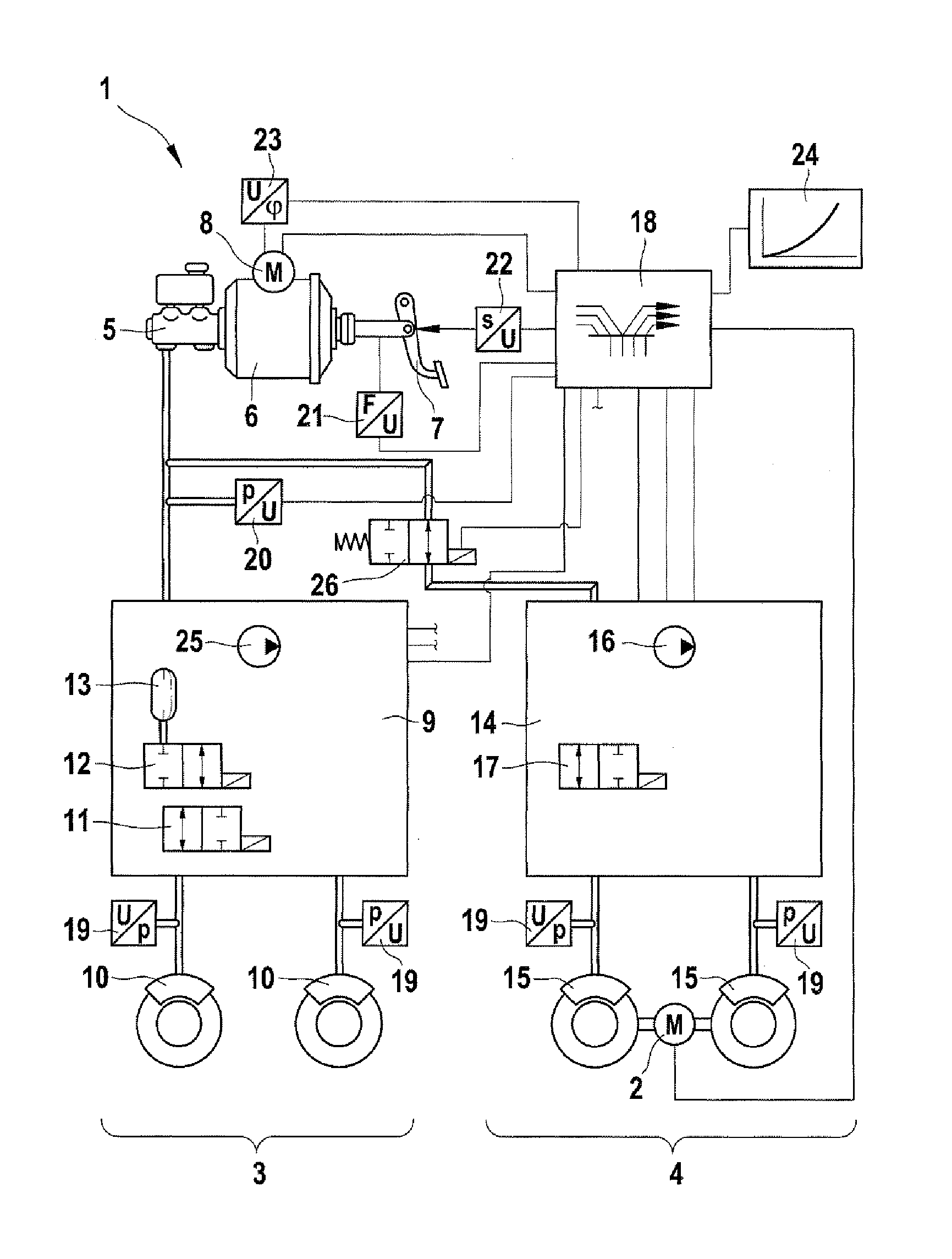
[0010]The inventive brake system 1, which is illustrated in the FIGURE, is provided for a motor vehicle (not illustrated) with drive by means of an electric drive motor 2. In the exemplary embodiment, the electric drive motor 2 acts on the two wheels of a vehicle axle, for example the rear axle. The electric drive motor 2 can also act on all the vehicle wheels, and a separate electric drive motor is also possible for each driven vehicle wheel. For the purpose of braking, the electric drive motor 2 can be operated as a generator. The motor vehicle can have an exclusively electro-motive drive; and it can also be what is referred to as a hybrid vehicle with a drive by means of an internal combustion engine (not illustrated) and the electric drive motor 2, wherein the drive can be provided by the internal combustion engine, the electric drive motor 2, or for example by means of both in order to provide strong acceleration, depending on the driving state and the driver's wishes. Although...


PUM


Abstract

A brake system for a motor vehicle includes a muscular power-operated or auxiliary power-operated brake system having a master brake cylinder which is operated by muscular power and which is connected to at least one hydraulic wheel brake, and an externally powered brake system having a hydraulic pressure source which is operated by external power and which is connected to the at least one hydraulic wheel brake. The brake system allows for an unchanged pedal characteristic in a hybrid vehicle which has an electric drive motor in addition to a combustion engine, which motor is used as a generator when the brake is actuated.

Description

PRIOR ART[0001]The invention relates to a brake system for a motor vehicle having a hydraulic muscle-power-operated or auxiliary-power-operated brake system having the features of the preamble of claim 1, and to a method for controlling said brake system having the features of the preamble of claim 6. “Controlling” in the sense of the invention is understood to mean “open-loop controlling” as well as “closed-loop controlling”.[0002]Laid-open patent application DE 103 19 663 A1 discloses a brake system for a motor vehicle which has a hydraulic auxiliary-power-operated brake system and an electromechanical externally powered brake system. The auxiliary-power-operated brake system acts, for example, on wheels of a front axle, and the externally powered brake system acts, for example, on wheels of a rear axle of the motor vehicle. The auxiliary-power-operated brake system is of a design known per se and has a master brake cylinder which can be activated by muscle force, for example by a...

Claims


Application Information

Patent Timeline
IPC IPC(8): B60T13/74B60T13/66
CPCB60T1/10B60T8/4072B60T2270/602B60T13/745B60T13/586B60T13/58B60T13/74B60T13/686
Inventor VOLLERT, HERRBERTWEIBERLE, REINHARDKUNZ, MICHAELKOLARSKY, JENS
Owner ROBERT BOSCH GMBH
Why Eureka
Try Eureka