Mobile wireless terminal and antenna device

a mobile wireless terminal and antenna device technology, applied in the direction of antennas, antenna details, elongated active element feed, etc., can solve the problems of disadvantageous occupying a large space, high antenna efficiency in an upper hemisphere, and difficult to intentionally control the directivity of typical /4 monopole antennas such as the above-described one, etc., to achieve excellent antenna directivity, narrow space, and simple structure

Inactive Publication Date: 2011-10-13
SONY CORP
View PDF1 Cites 53 Cited by
  • Summary
  • Abstract
  • Description
  • Claims
  • Application Information

AI Technical Summary

Benefits of technology

[0021]Antenna devices according to embodiments of the present invention and mobile wireless terminals including the antenna elements can eliminate nulls in an antenna characteristic patter

Problems solved by technology

Intentionally controlling a directivity of typical λ/4 monopole antennas, such as the above-described one, is difficult because the size of a plate greatly affects the directivity.
However, the directivity of the GPS antennas often points to the surface of the Earth.
(1) Directivity of the GPS antennas points to the sky. That is, antenna efficiency in an upper hemisphere is high.
(2) Directivity of the GPS antennas is free from nulls (where antenna efficiency gre

Method used


Image

  • Mobile wireless terminal and antenna device
  • Mobile wireless terminal and antenna device
  • Mobile wireless terminal and antenna device

Examples


Embodiment Construction

[0039]Mobile wireless terminals according to embodiments of the present invention will be described in detail below with reference to the accompanying drawings. In the embodiments, the description is mainly given for a mobile phone terminal having a GPS antenna, for example.

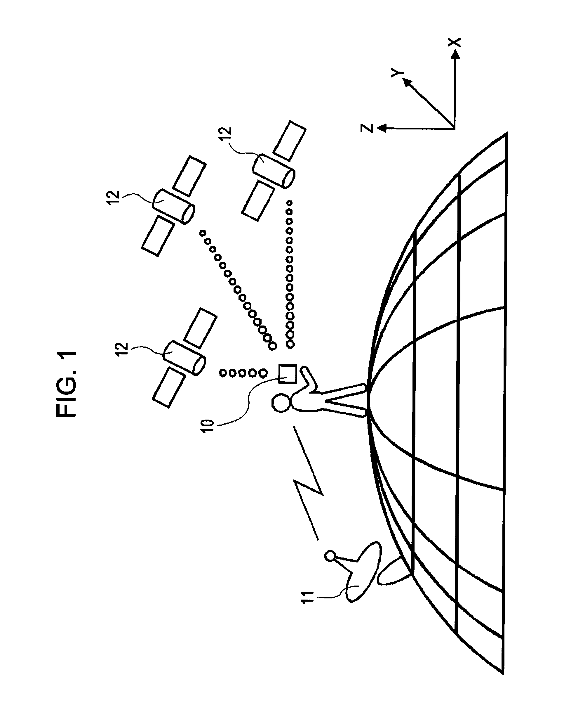
[0040]FIG. 1 illustrates a state of a mobile wireless terminal 10 being used by a user. The mobile wireless terminal 10 transmits and receives radio signals (radio waves) to and from a base station 11 located on the ground, respectively. The mobile wireless terminal 10 also receives radio signals (radio waves) from a plurality of GPS satellites 12 located in the space.

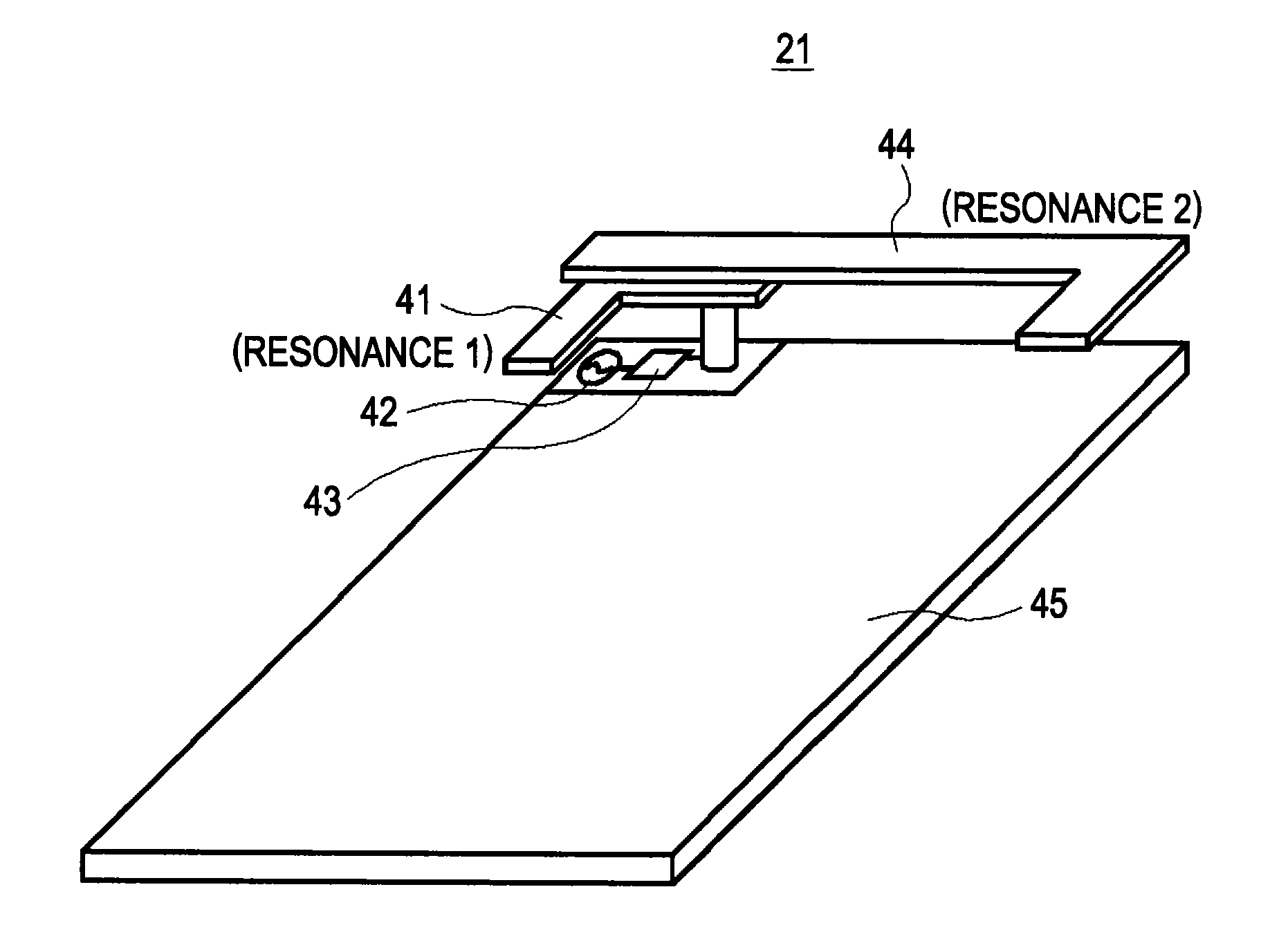
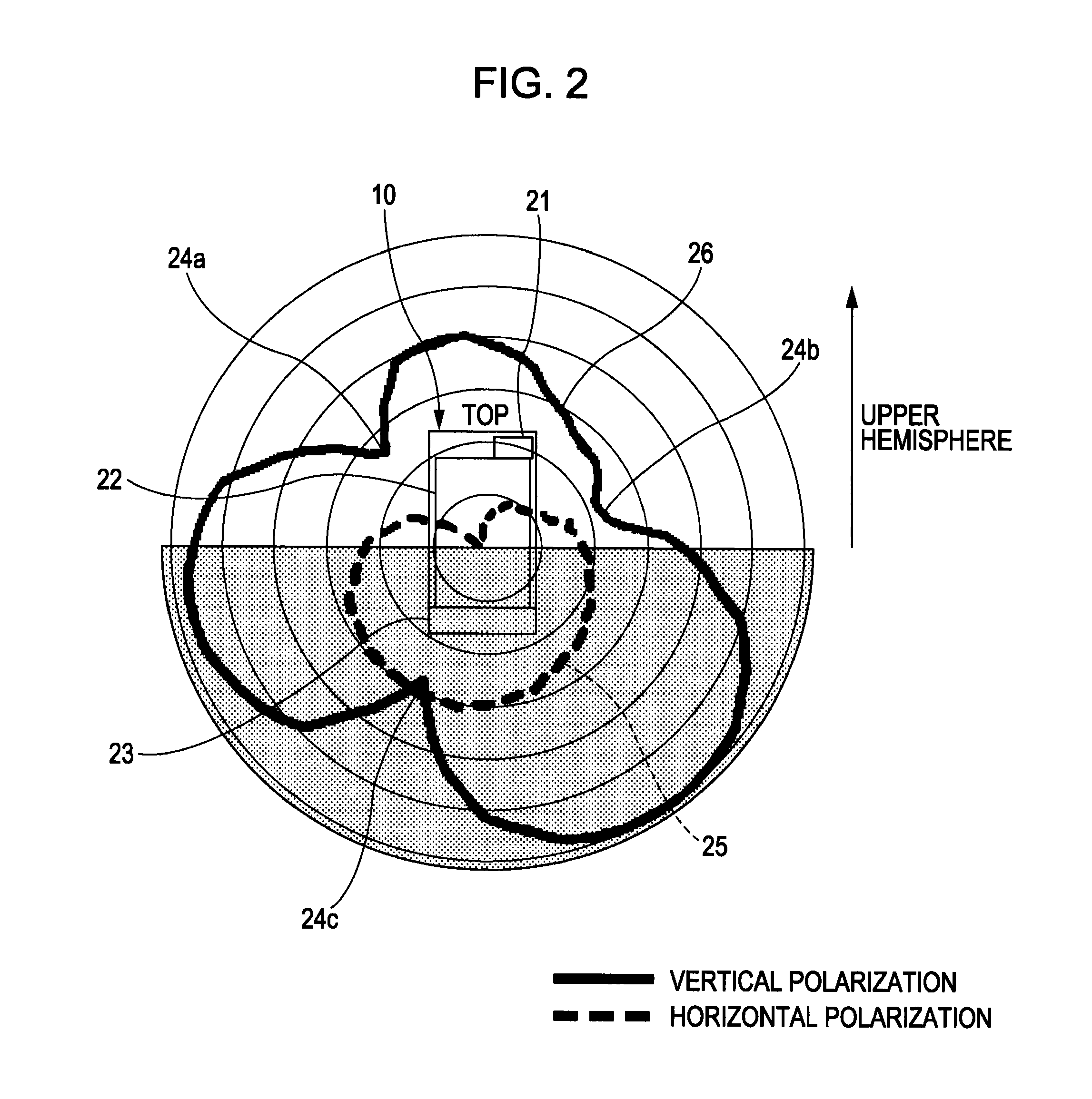
[0041]FIG. 2 illustrates the mobile wireless terminal 10 held by a user standing on the ground and an antenna characteristic pattern thereof. In this example, the mobile wireless terminal 10 includes a liquid crystal display (LCD) 22 serving as a display unit and an antenna device 21 serving as a GPS antenna. The antenna device 21 is disposed above ...


PUM


Abstract

A mobile wireless terminal includes a housing, a cover removably attached to the housing, and an antenna device disposed inside the housing. The antenna device includes a first antenna element that is disposed inside the housing and serves as a feed element, a plate that provides a ground plane for the first antenna element, and a second antenna element that is formed on one surface of the cover so as to face the first antenna element with the cover being attached to the housing and capacitively couple to the first antenna element and that serves as a parasitic element.

Description

CROSS REFERENCE TO RELATED APPLICATION[0001]The present application claims the benefit of the earlier filing date of U.S. Provisional Patent Application Ser. No. 61 / 322,494 filed Apr. 9, 2010, the entire contents of which being incorporated herein by reference.BACKGROUND[0002]1. Technical Field[0003]The present invention relates to mobile wireless terminals, such as mobile phone terminals, and antenna devices thereof.[0004]2. Description of the Related Art[0005]Recently, the performance and the number of functions of mobile wireless terminals, such as mobile phone terminals, have been increased. Mobile wireless terminals are emerging that make wireless communication functions, such as functions of telephone communication, data communication, the global positioning system (GPS), a wireless local area network (LAN), and BLUETOOTH available.[0006]One type of antenna for use in such wireless communication is a λ / 4 monopole antenna including a plate and an antenna element having a length...

Claims


Application Information

Patent Timeline
IPC IPC(8): H01Q1/24
CPCH01Q1/243H01Q9/40H01Q5/385H01Q19/005H01Q5/378H01Q9/42H01Q5/0062H01Q5/0065
Inventor BUNGO, AKIHIROKUSAMA, TOSHIYA
Owner SONY CORP
Why Eureka
Try Eureka