
Automatic road mapping for heart valve replacement

a technology for heart valves and road mapping, applied in the field of automatic road mapping for heart valve replacement, can solve the problems of inaccurate positioning of prostheses, process errors, and staff carrying out operations, and achieve the effect of better information

Active Publication Date: 2011-10-13
KONINKLIJKE PHILIPS ELECTRONICS NV
View PDF10 Cites 18 Cited by
  • Summary
  • Abstract
  • Description
  • Claims
  • Application Information

AI Technical Summary

Benefits of technology

The present invention provides an examination apparatus and method for automatic road mapping for heart valve replacement. The invention aims to provide better information to cardiologists and surgeons during heart valve replacement procedures. The invention involves acquiring images of the vessel root region and using them to model the vessel root representation. The model is then combined with a fluoroscopy image to create a composite image. The composite image is displayed on a display for easy viewing by the operator. The invention can be used for any type of heart valve replacement and does not require any manual intervention. The outline of the vessel root can be easily detected and segmented from the image. The invention provides a simplified structure of the valve's surrounding anatomy as displayed in a CA-filled sequence. The technical effects of the invention include improved accuracy in positioning the artificial valve and easier placement of the catheter device.

Problems solved by technology

But still, one of the main difficulties the staff carrying out the operation faces during PHV implantation is the accurate positioning of the prosthesis.
It has shown that this mental process is prone to error and makes the positioning a delicate and tiring operation.

Method used


Image

  • Automatic road mapping for heart valve replacement
  • Automatic road mapping for heart valve replacement
  • Automatic road mapping for heart valve replacement

Examples


Embodiment Construction

[0043]In the following, the invention is exemplarily described in relation with the replacement of the aortic valve. But the invention is also focussed on the replacement of other types of heart valves, such as pulmonary, mitral and tricuspid valves. Hence, in the following the term aortic root region is used instead of vessel root region or valve vicinity (area surrounding the annulus that is visible after contrast injection; this can be a vessel root (aortic, pulmonary), and / or the annulus walls on the surface of one or two cardiac chambers), the term aortic information data instead of vessel information data and the term aortic root representation also stands for vessel root representation. Anyway, it is clear that the scope of the invention covers other type of heart valves as well.

[0044]In FIG. 6a heart 110 is shown with a right part 112 and a left part 114 in relation to the main vessels. The right part 112 is placed on the vena cava in the diagram. It should designate the par...


PUM

PropertyMeasurementUnit
vessel structureaaaaaaaaaa
currentaaaaaaaaaa
greyscale fluoroscopyaaaaaaaaaa

Abstract

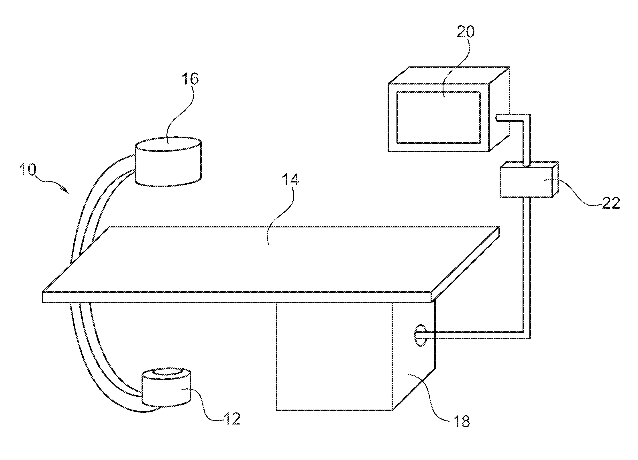
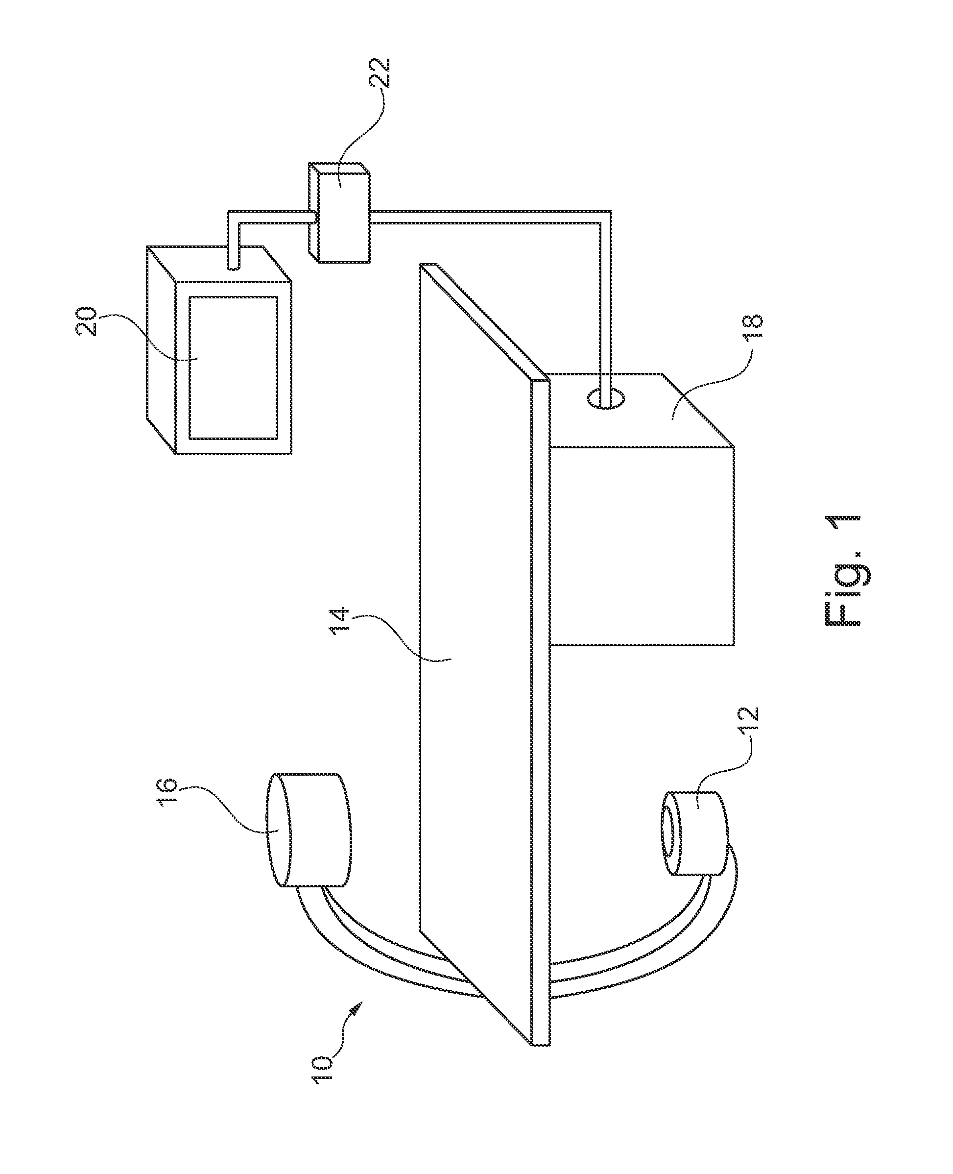
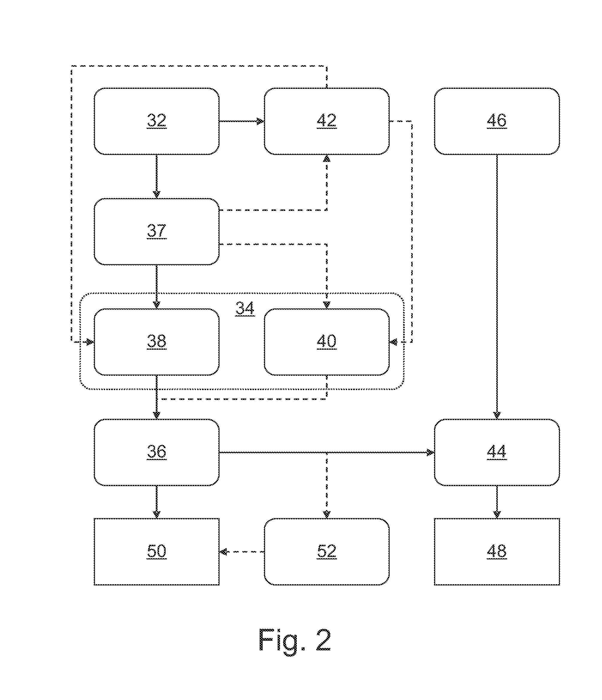
The present invention relates to a method for automatic road mapping for heart valve replacement and an examination apparatus for automatic road mapping for heart valve replacement. In order to provide the cardiologist or surgeon with better information during PHV implantation, an examination apparatus for automatic roadmapping for heart valve replacement is provided, that comprises at least one X-ray image acquisition device (10), a calculation unit (18) and a display device (20). The image acquisition device is adapted to acquire (32) at least one X-ray image of a vessel root region of a heart with injected contrast agent and to acquire (46) at least one current fluoroscopy image of the vessel root region with a replacement valve inserted into the vessel. The calculation unit is adapted to identify (34) vessel information data within the at least one acquired image, to model (36) vessel root representation using the vessel information data and to generate (44) a composite image by a combination of the model of the vessel root representation with the at least one fluoroscopy image. The display unit is adapted to display (48) the composite image.

Description

FIELD OF THE INVENTION[0001]The present invention is related to a method for automatic road mapping for heart valve replacement and an examination apparatus for automatic road mapping for heart valve replacement amongst others.BACKGROUND OF THE INVENTION[0002]Treatment of heart valve problems or heart valve diseases is becoming more important because of an ageing population. Such diseases, for example aortic stenoses, usually require the replacement of a native heart valve, for example of the aortic valve, which is the most important and thus most critical valve of the human heart. The valve replacement can be done in two different ways, for example. The surgical valve replacement is considered as a “gold standard” treatment. As an alternative, the so-called percutaneous valve replacement is a fairly new intervention that is increasingly applied. Percutaneous valve replacement usually includes transcatheter heart valve implantation. With this method the valve can be placed either th...

Claims


Application Information

Patent Timeline
Patent Type & Authority Applications(United States)
IPC IPC(8): G01N23/04
CPCA61B6/12G06T2207/30101A61B6/481A61B6/503A61B6/504A61B6/5235A61B2017/00243A61B2019/5238A61F2/24G06T7/0012G06T2207/10116G06T2207/10121G06T2207/20212G06T2207/30048A61B6/463A61B2090/376A61B2034/105
Inventor FLORENT, RAOULBAKKER, NICOLAAS HYLKE
Owner KONINKLIJKE PHILIPS ELECTRONICS NV
Learn More