Thermographic Imaging Element
a technology of thermal imaging and elements, applied in thermography, duplicating/marking methods, printing, etc., can solve the problems of printing technology with significant weakness, stable printing image to fade, and rapid fade of labels, facsimiles and receipts printed on direct thermal sensitive substrates
- Summary
- Abstract
- Description
- Claims
- Application Information
AI Technical Summary
Problems solved by technology
Method used
Image
Examples
example 1
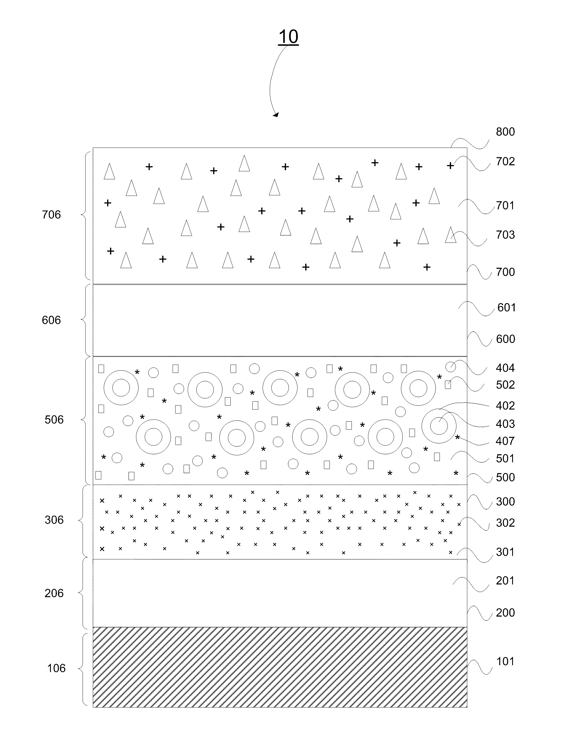
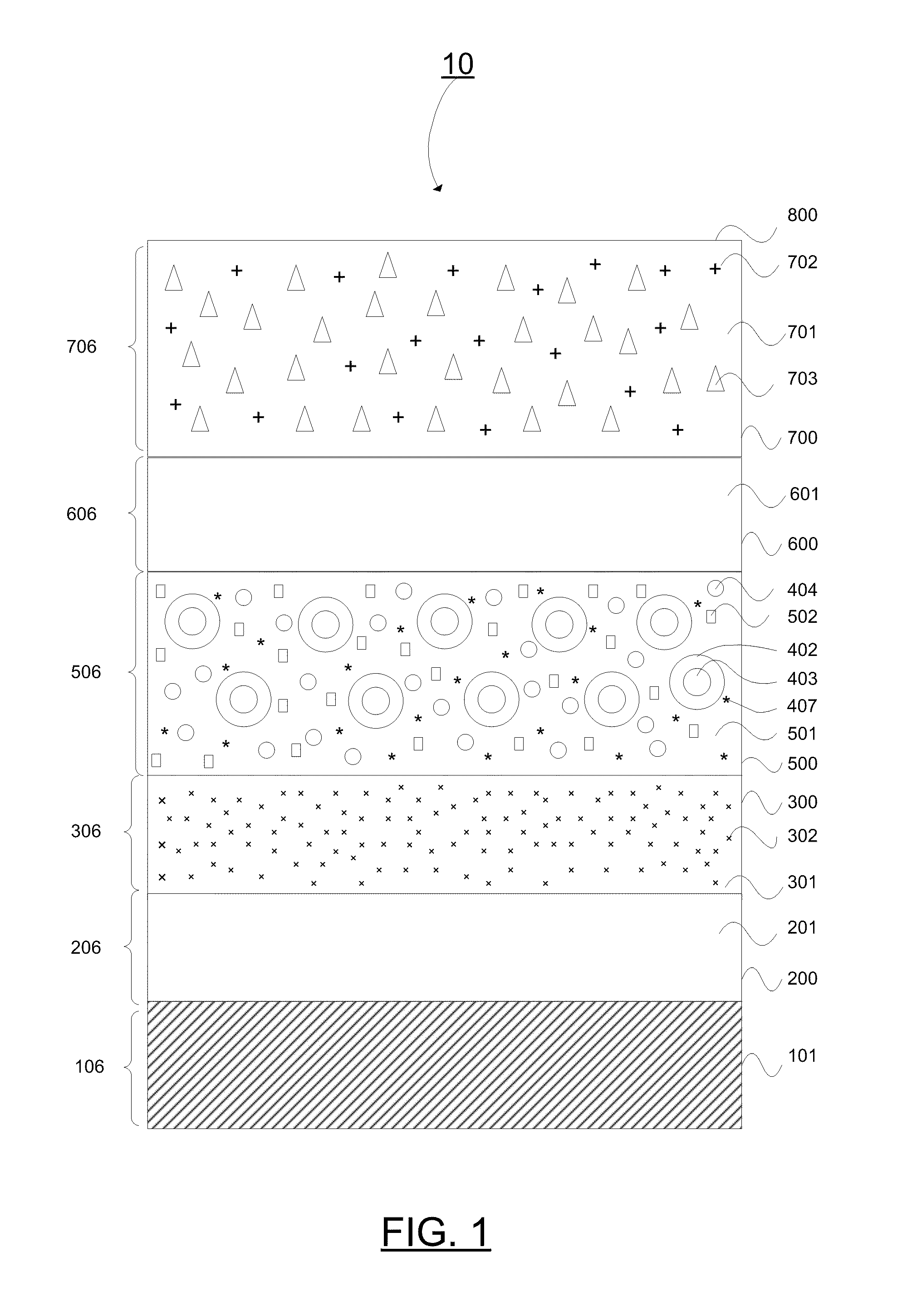
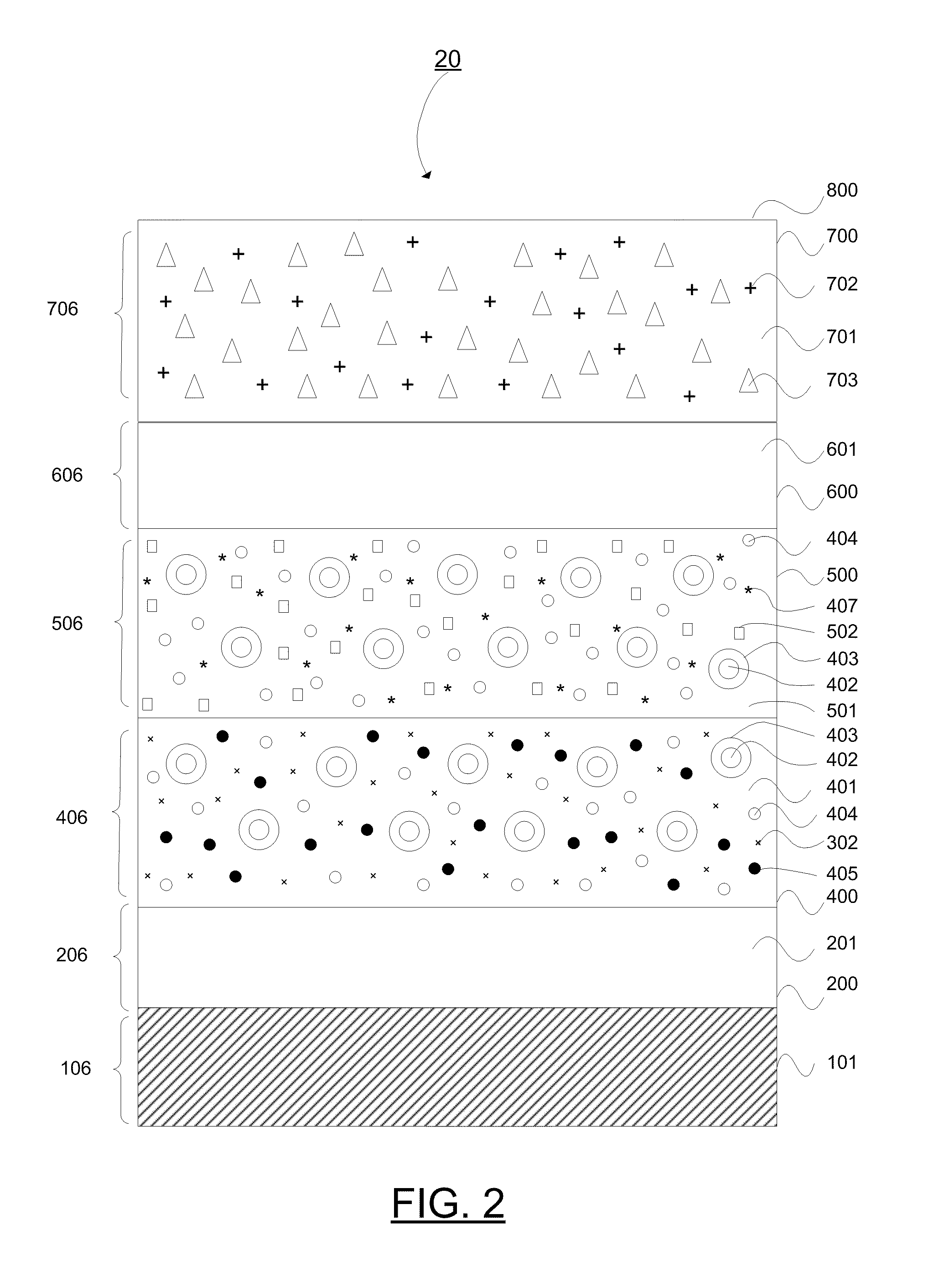
[0331]This example illustrates the preparation of a thermographic substrate that comprises a base polyester flexible substrate (sold as part number “21940 THERMLfilm SELECT “by (FIexCON Inc of Spenser, Mass.), a color (black) layer, a thermo-sensitive opaque (white) layer, and a heat resistant topcoated layer that together will, when heated to a temperature range produced by a thermal printer printhead, produce a visually contrasting colored (black), image.
[0332]In the experiment described by this example, a black nitrocellulose gravure color ink was applied to the polyester substrate using a #4 Meyer rod for an average wet coverage of 3.57 grams per square meter, and it was allowed to dry, resulting in a black color layer with a dry coverage of 1.07 grams per square meter.
[0333]In such experiment, the black color layer coated on the polyester substrate was measured for reflective density (Rd) using a MacBeth (Grandville, Mich.) model RD914 densitometer. The Rd of the black color la...
example 2
[0340]This example illustrates the preparation of a thermographic substrate that consists of a polyester flexible substrate (21940 THERMLfilm), a black color layer, an opaque (white) thermosensitive layer, and a heat resistant topcoating that together will, when heated to a temperature range, produce a visually colored (black) image.
[0341]The black color layer described in Example 1 was coated onto the polyester substrate via drawdown rod #4 and dried, and the reflective density was measured to be 1.8.
[0342]A white opaque thermosensitive coating ink having the following composition was prepared: 12.45 grams of a 30 percent styrene / acrylic hollow organic pigment dispersion in water known as “Ropaque 0-96” was added to a small plastic mixing vessel. To this, 2.08 grams of a 40 percent dispersion in water of dibenzyl oxalate thermal solvent (HS-2046), 2.78 g of a wax binder (a 30 percent Carnauba wax dispersion in water obtained from Koster Keunen, LLC, 1021 Echo Lake Rd., Watertown, C...
example 3
[0344]Sample thermosensitive coatings comprised of combinations of five different hollow organic pigments and five different thermal solvents were evaluated for transparentization as a function of temperature. The following hollow organic pigments were used:
TABLE 1Hollow Organic Pigments of Example 3wetdryper-Organicgrams / grams / PScentPigmentSupplierresinccccμvoidRopaqueRohm&Haasstyrene / 1.030.630.542OP-96acrylateHique 168Nae Woistyrene / 1.020.5acrylateHique 332Nae Woistyrene / 1.030.4acrylateHique332LNae Woistyrene / 1.030.4acrylateHique2050Nae Woistyrene1.021.2
The following thermal solvents, ranging in solubility parameter from 15.3 Megapascals1 / 2 to 29.9 Megapascals1 / 2 in Table 2 were used.
TABLE 2Thermal Solvents Used in Example 3Thermal Solventδ MPa1 / 2SupplierLocationEthylene Glycol29.9Univar Inc.Tonawana, NYDipropylene Glycol20.5Dow Corp.Midland, MIDibenyl oxalate16.6DIC Corp.Osaka, Japan(HS2046)Butyl Stearate15.3Sigma-AldrichSt. Louis, MO
[0345]Samples were prepared by mixing 3 grams ...
PUM
| Property | Measurement | Unit |
|---|---|---|
| particle size | aaaaa | aaaaa |
| melting points | aaaaa | aaaaa |
| particle size | aaaaa | aaaaa |
Abstract
Description
Claims
Application Information
 - R&D
- Intellectual Property
- Life Sciences
- Materials
- Tech Scout
- Unparalleled Data Quality
- Higher Quality Content
- 60% Fewer Hallucinations
Browse by: Latest US Patents, China's latest patents, Technical Efficacy Thesaurus, Application Domain, Technology Topic, Popular Technical Reports.
© 2025 PatSnap. All rights reserved.Legal|Privacy policy|Modern Slavery Act Transparency Statement|Sitemap|About US| Contact US: help@patsnap.com


