Brake bleeding apparatus
- Summary
- Abstract
- Description
- Claims
- Application Information
AI Technical Summary
Benefits of technology
Problems solved by technology
Method used
Image

Examples
Embodiment Construction
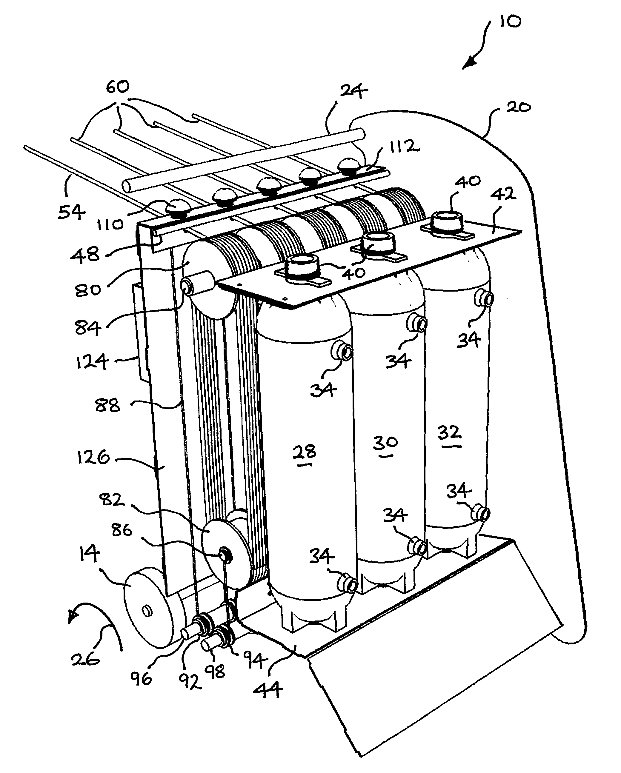
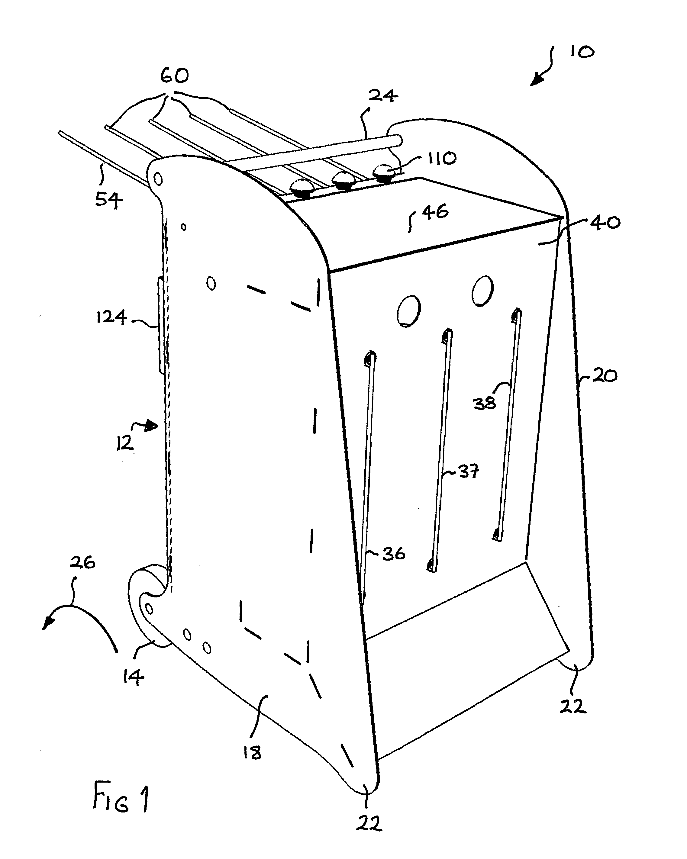
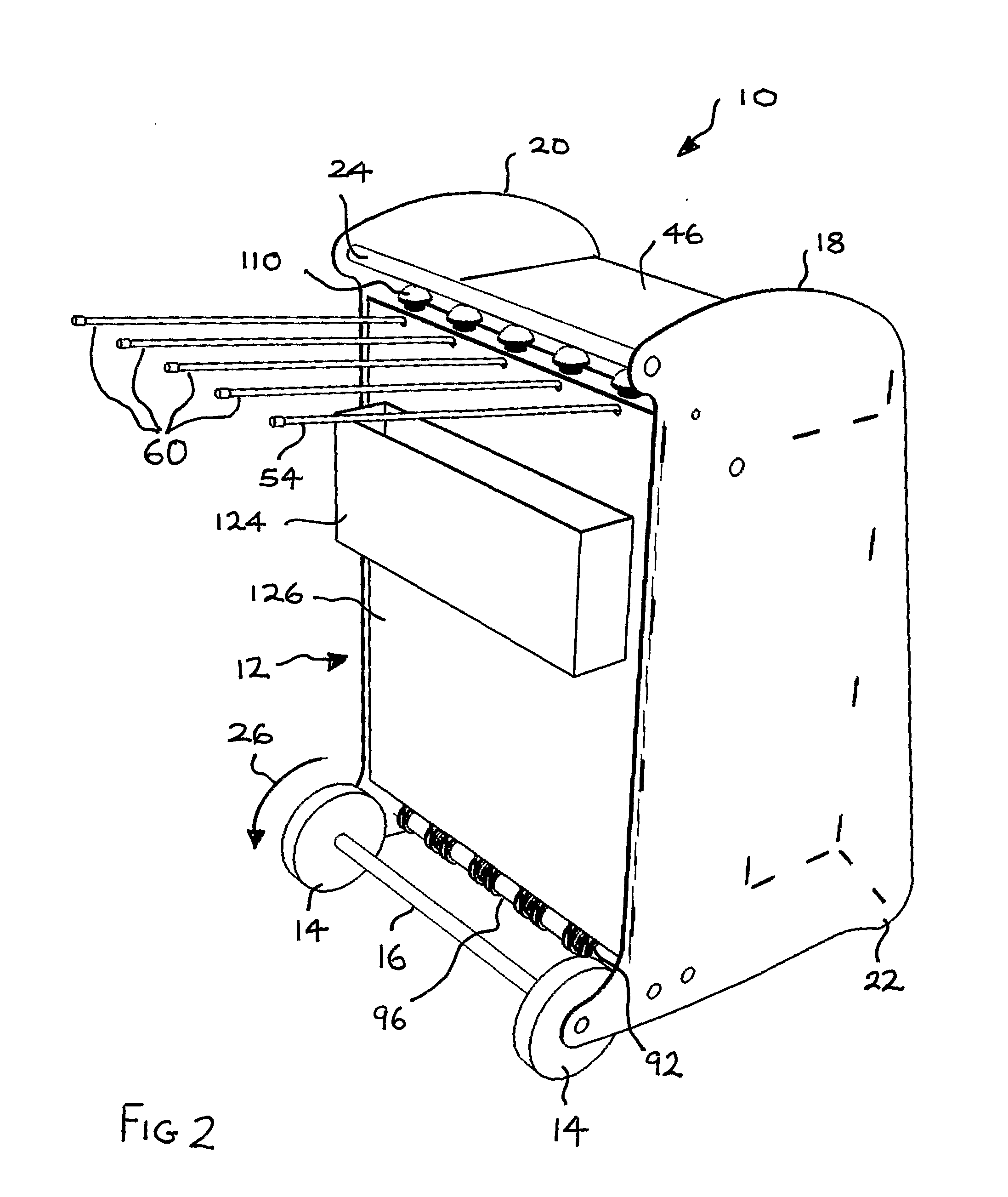
[0021]Referring to FIGS. 1 to 3, a brake bleeding apparatus 10 comprises a wheeled cabinet 12. The cabinet 12 has two wheels 14 provided on an axle 16 (FIG. 2). The axle 16 is fitted to respective rearward protrusions defined at the bottom rear of opposed side panels 18, 20 of the cabinet 12. The cabinet 12 has feet 22 provided generally opposite the wheels 14 at the bottom front of the side panels 18, 20. The feet 22 may be parts fitted to the side panels 18, 20. In the illustrated embodiment, the feet 22 are defined by forward protruding portions of the side panels 18, 20. A push handle 24 is provided at the top rear of the cabinet 12 generally above the wheels 14. The push handle 24 is a generally circular section rod that is fitted between respective rearwardly projecting ears defined by the side panels 18, 20. A user can readily move the brake bleeding apparatus 10 from place to place by standing to the rear of the cabinet 12, grabbing the push handle 24 and pivoting the cabine...
PUM
| Property | Measurement | Unit |
|---|---|---|
| Force | aaaaa | aaaaa |
| Pressure | aaaaa | aaaaa |
| Flow rate | aaaaa | aaaaa |
Abstract
Description
Claims
Application Information
 - R&D Engineer
- R&D Manager
- IP Professional
- Industry Leading Data Capabilities
- Powerful AI technology
- Patent DNA Extraction
Browse by: Latest US Patents, China's latest patents, Technical Efficacy Thesaurus, Application Domain, Technology Topic.
© 2024 PatSnap. All rights reserved.Legal|Privacy policy|Modern Slavery Act Transparency Statement|Sitemap