Robotic cell

a robot and cell technology, applied in the field of robot cells, can solve the problems of assembly failure, less advantageous use of robot stations, lower workability, etc., and achieve the effect of high rigidity and high maintainability of a trestl

Inactive Publication Date: 2011-10-27
CANON KK
View PDF30 Cites 29 Cited by
  • Summary
  • Abstract
  • Description
  • Claims
  • Application Information

AI Technical Summary

Benefits of technology

[0013]The present invention has an object to provide a robotic cell that enables in particular both high maintainability and high rigidity of a trestle to be attained in downsizing a robotic station.

Problems solved by technology

Even in the case of the robotic station that may be used for general purposes, if the robotic station occupies a larger area than that of a manual assembly line or if it takes longer time than manual work, the use of the robotic station is less advantageous.
However, those robotic stations are designed as production systems focusing on easiness of movement and process change, and hence there are the following unaddressed problems.
As a result, the volume of the trestle is limited, and accordingly, when the robotic station is downsized, a space for maintenance of the control portions cannot be ensured as the volume is reduced, which lowers workability.
The decrease in rigidity causes the trestle itself to vibrate due to the operation of the robot, and the vibration is therefore intense at the distal end portion of the robotic arm, with the result that failure occurs in assembly, transport, and the like.
Further, it takes time to stabilize the vibration at a desired amplitude, which leads to an increase in tact time and other troubles.
Further, in a case where an auxiliary member is provided so as to cover the cut-out portion for preventing the decrease in rigidity, it is necessary to detach the auxiliary member every time the trestle is accessed, with the result that the maintainability decreases.
As described above, it is difficult to attain both high maintainability and high rigidity of the trestle.
Further, in the robotic station disclosed in Japanese Patent Application Laid-Open No. 2008-229738, the trestle includes the wheeled platform on the bottom portion thereof, and hence, even though the trestle itself has rigid structure, the rigidity cannot be ensured with respect to a floor.
Because the wheeled platform is provided, the trestle itself is unstable and the volume of the housing in the trestle is also limited.
Hence, similarly to the case of Japanese Patent Application Laid-Open No. 07-001298, there is a problem that the downsizing of the robotic station and both high maintainability and high rigidity cannot be attained.

Method used


Image

  • Robotic cell
  • Robotic cell
  • Robotic cell

Examples


first embodiment

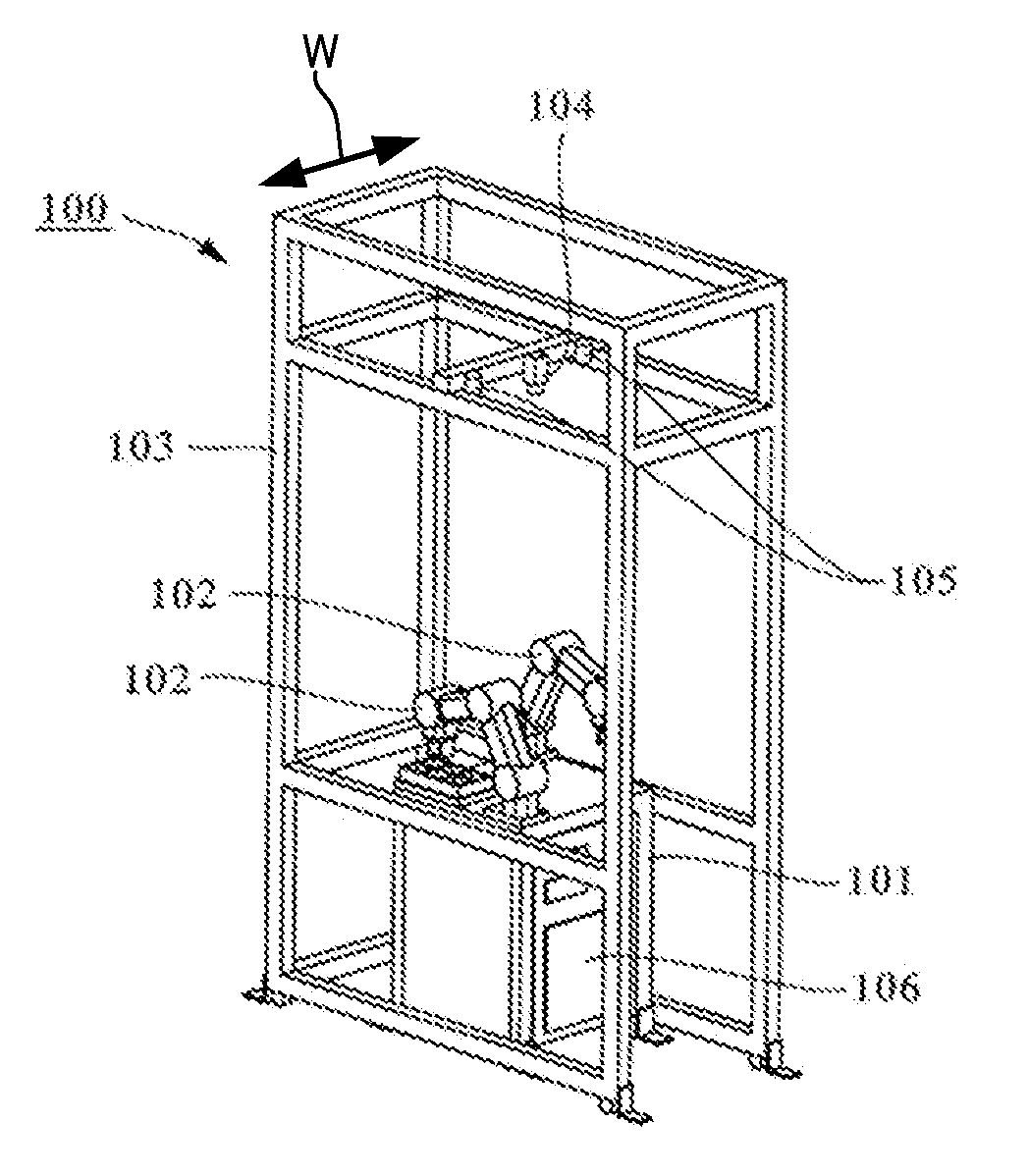
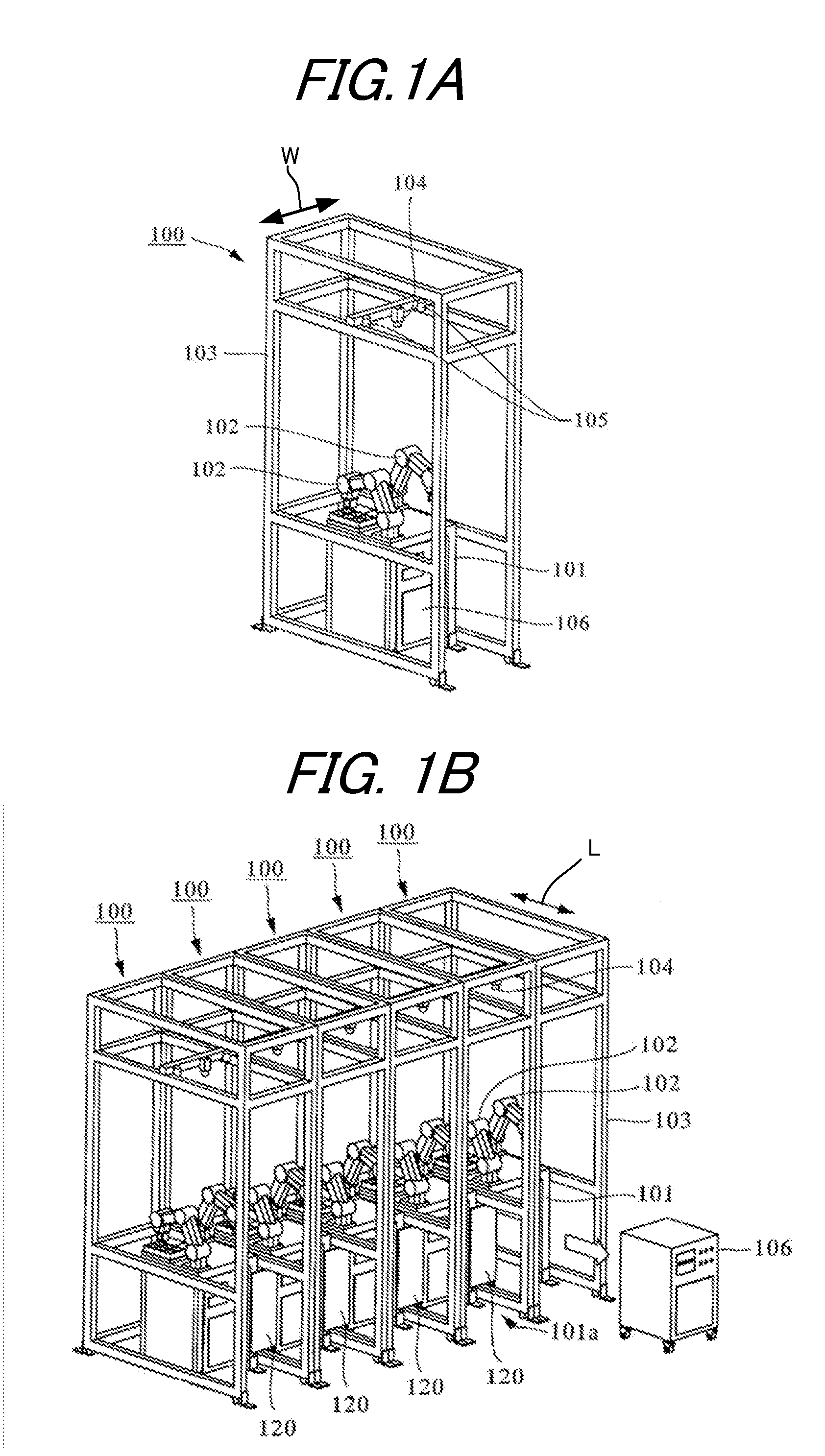
[0023]FIGS. 1A and 1B illustrate a robotic cell according to a first embodiment of the present invention. This apparatus is configured by combining multiple robotic stations 100 on each of which a robot for assembling parts is mounted. Referring to FIG. 1A, each robotic station 100 mainly includes a trestle 101, a pair of robotic arms 102 constituting the robot, a booth 103, a camera 104, and illumination lamps 105. Referring to FIG. 1B, the robotic cell serving as a serial production system is built by combining the multiple robotic stations 100.

[0024]Each booth 103 is a frame constructed by rigid pillars so that the trestle 101 is housed therein and the camera 104 is fixed thereto in order to measure the position and posture of workpieces and fed parts in a work space on the trestle. A width of the booth 103 in a width direction W is set to a value enough to space apart the trestle 101 and each pillar of the booth 103 with no contact therebetween. Further, a length of the booth 10...

second embodiment

[0035]FIG. 4 illustrates a robotic cell according to a second embodiment of the present invention. The second embodiment is different from the first embodiment only in that a connecting member 130 is used. The connecting member 130 is different from the connecting member 120 in the method for connection to the pillars 111 of the trestles 101 of the adjacent robotic stations 100. In this embodiment, the connecting member 130 is arranged between the pillars 111 of the adjacent trestles 101. Then, both end portions 130a of the connecting member 130 are respectively brought into surface contact with opposing surfaces 111a of the pillars 111, and those components are fastened to each other. Accordingly, the adjacent trestles 101 are rigidly coupled to each other to increase the rigidity of the trestles 101.

[0036]In a case where two opening portions are provided on two side surfaces of each trestle, respectively, one more connecting portion using the connecting member is only added, and t...


PUM

PropertyMeasurementUnit
volumeaaaaaaaaaa
speedaaaaaaaaaa
areaaaaaaaaaaa

Abstract

A robotic cell enables a robotic station to be downsized and both high maintainability and high rigidity to be attained. To this end, the robotic cell for assembling parts by using multiple robots includes multiple booths for housing multiple trestles, on each of which a pair of robotic arms are mounted, with the trestles adjoining one another. Each trestle has an opening portion on one side surface thereof, through which a power controller box is carried in and out. To compensate for a decrease in rigidity of the trestle due to the opening portion, a connecting member is used for coupling two trestles adjacent to each other across the respective booths. Both end portions of each connecting member are fastened to the both trestles with screws, respectively.

Description

BACKGROUND OF THE INVENTION[0001]1. Field of the Invention[0002]The present invention relates to a robotic cell which is configured by combining general-purpose unitized assembly apparatuses (robotic stations) including robots to be incorporated in a production system.[0003]2. Description of the Related Art[0004]In recent years, small-size electric products and electronic products have increasingly been produced in a style of low-volume, high-variety production in a shorter product life cycle. Further, line layout of a production line for those products tends to be changed frequently so as to suit the kind of product to be produced. When the production line is shifted to another kind of product, it takes time to change the line layout and dedicated tools need to be prepared therefor. Hence, except that a certain volume of products are produced collectively, manual cell production is conducted in many cases in place of automated production. In recent years, however, even in such a ca...

Claims


Application Information

Patent Timeline
Patent Type & Authority Applications(United States)
IPC IPC(8): B23P19/00
CPCB23P19/00B23P21/00Y10T29/53B25J9/0084B25J21/00B25J9/0009
Inventor MEISHO, KENNAKASUGI, MIKIONEGISHI, MAHITOMATSUO, YUJI
Owner CANON KK
Why Eureka
Try Eureka