Stretch-blow molding machine

a molding machine and bending technology, applied in the direction of auxillary shaping apparatus, other domestic objects, manufacturing tools, etc., to achieve the effect of easy absorption of even high forces

Inactive Publication Date: 2011-10-27
KRONES AG
View PDF3 Cites 30 Cited by
  • Summary
  • Abstract
  • Description
  • Claims
  • Application Information

AI Technical Summary

Benefits of technology

[0043]Furthermore, it can be suitable if the blow molding slide is taken along by the stretching rod or the stretching slide at least over a portion of the return stroke in the process, or if the stretching slide is terminated by the blow molding slide during the return stroke of the stretching rod while the servomotor is then de-energized, while the blow molding slide is at this point in time mechanically locked in the blow molding station and can easily absorb even high forces.
[0044]The use of the computerized electronic control unit in the blow molding station permits to record and visualize directly at the control unit or at an external master control system the stretching path, the stretching force, the blow pressure, the stretching speed and the like each in a separate diagram, e.g. over time, or the angle of rotation of the rotating part (for example in a touch screen), or to superimpose it on the blow curve recording. This provides the operator with additional information for precise process control and optionally for suitable correction measures. Envelopes or limiting values for such parameters can also be entered, or suggested values with a certain tolerance range of for example ±10% can be automatically visualized by the control unit. An envelope can be used, for example, to automatically discard a produced container when the envelope is exceeded or not reached. The path control of the stretching rod can furthermore be coupled to a signal, for example to the signal which represents a valve switching or a pressure increase. This offers the advantage of compensating varying valve switching times in the production process.

Problems solved by technology

However, it is also conceivable not to drive the stretching rod to the upper position until a later point in time.

Method used


Image

  • Stretch-blow molding machine
  • Stretch-blow molding machine
  • Stretch-blow molding machine

Examples


Embodiment Construction

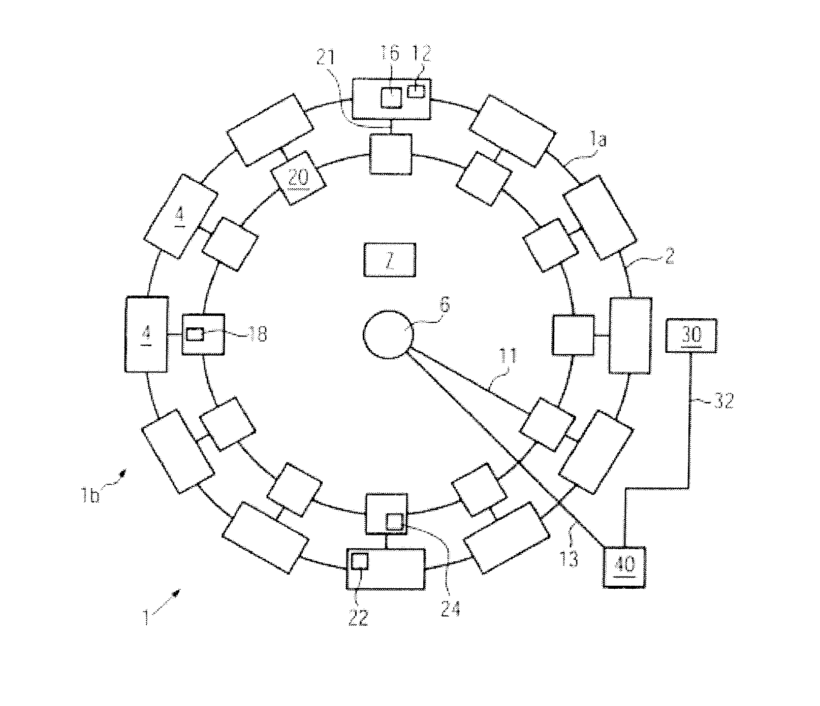
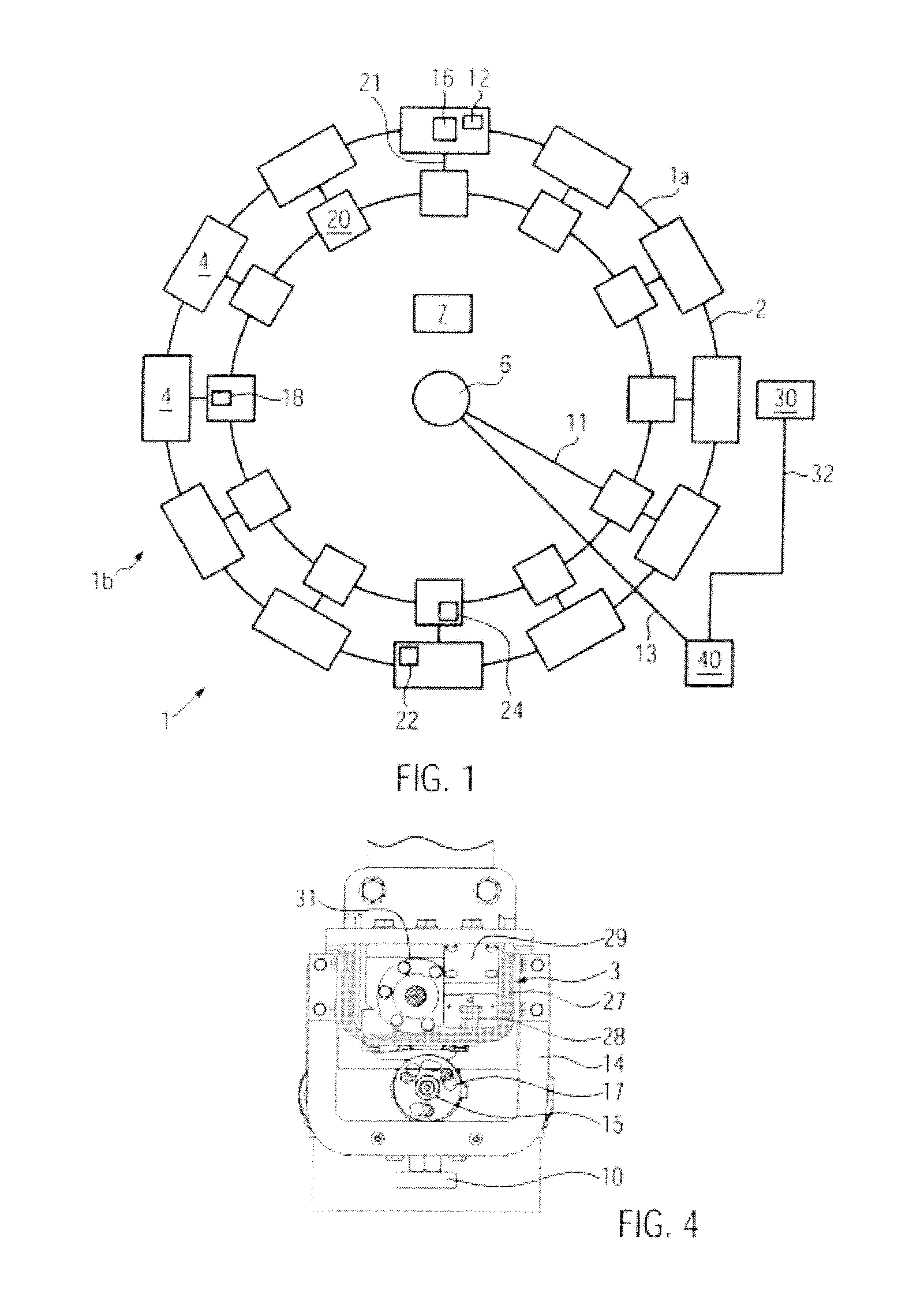
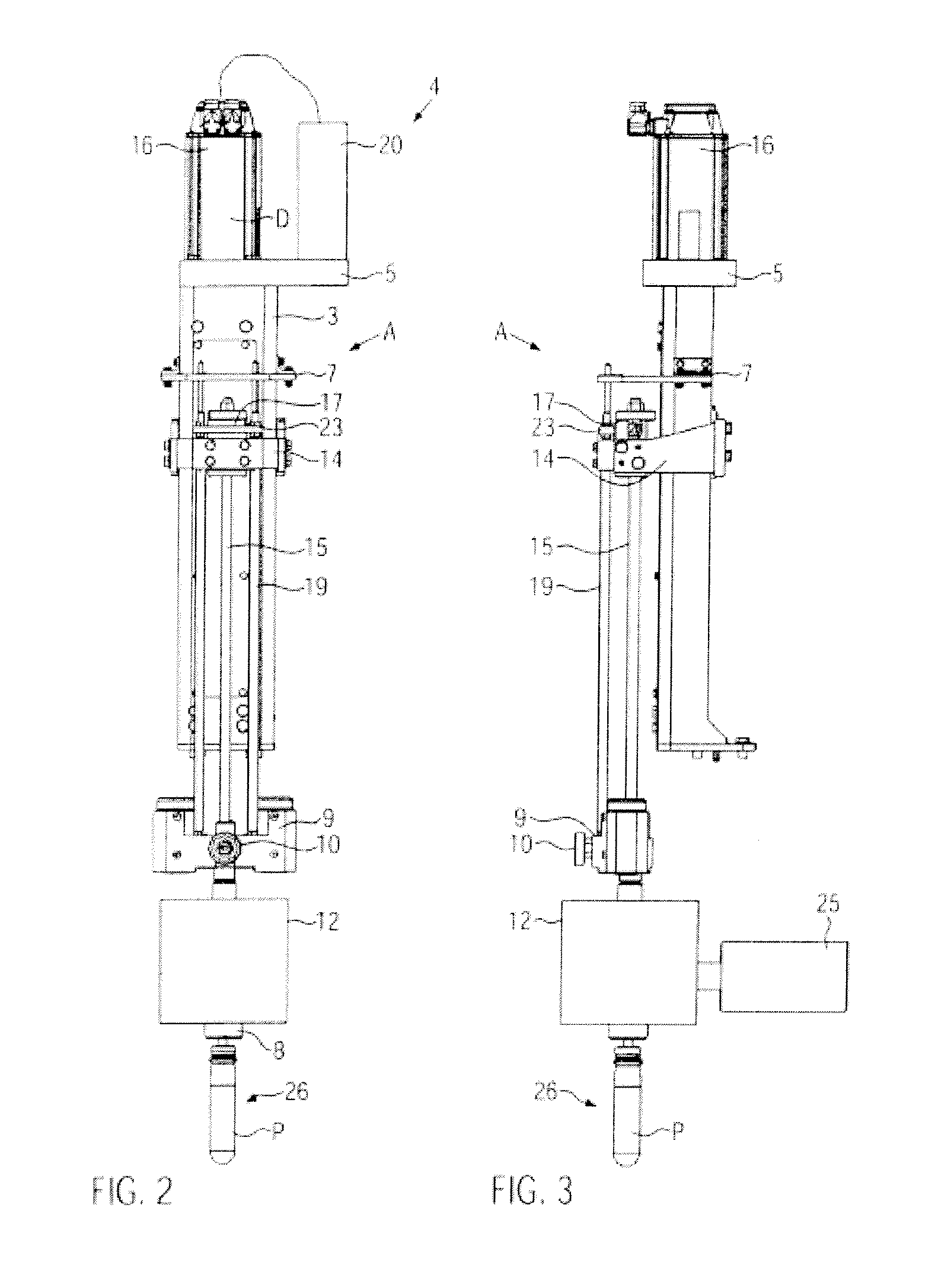
[0055]FIG. 1 schematically shows a stretch-blow molding machine 1 for stretch-blow molding containers from preforms. The stretch-blow molding machine 1 is a rotary-type machine with a blow-molding unit 2 supporting blow-molding stations 4 at its periphery which represents apart 1a rotating in relation to a stationary part 1b. The concept according to the disclosure, however, can be used without restrictions for stretch-blow molding machines in which the blow molding stations are arranged stationarily (not shown).

[0056]For at least one blow molding station 4, one electronic control unit 20 each is arranged on the blow-molding unit 2 in FIG. 1. The power supply of the control units 20 is accomplished e.g. via connection lines 11 and a rotary transmission leadthrough 6, e.g. a slip ring arrangement and / or a medium leadthrough, in the center of the blow-molding unit 2. Each blow molding station 4 has a stretching rod drive system, here with an electric servomotor 16, and a valve section...


PUM

PropertyMeasurementUnit
circuit voltageaaaaaaaaaa
voltageaaaaaaaaaa
circuit voltageaaaaaaaaaa

Abstract

A stretch-blow molding machine having at least one blow molding station, in which a split blow mold, an adjustable blow nozzle with a valve section, a stretching rod with a stretching rod drive system, and an electronic control unit are provided, the electronic control unit arranged in the blow molding station is equipped with hardware and software for selectively operating the blow molding station with a combination of a cam drive and a pneumatic drive, or a combination of an electric servo drive and a pneumatic drive, or only an electric servo drive in the stretching rod drive system. The movement of the stretching rod is initiated in the stretch-blow molding machine in the production process of a container by means of an electric servomotor with the beginning of or during the locking phase of the blow mold and before the blow nozzle is placed, and the stretching rod is already displaced to a position in which the stretching rod is either very closely approached to the preform bottom or contacts the preform bottom, or has even already pre-stretched the preform, until the blow nozzle is placed.

Description

CROSS-REFERENCE TO RELATED APPLICATION[0001]The present application claims the benefit of priority of German Patent Application No. 102010028255.3 filed Apr. 27, 2010. The entire text of the priority application is incorporated herein by reference in its entirety.FIELD OF THE DISCLOSURE[0002]The disclosure relates to a stretch-blow molding machine as well as to a method of stretch-blow molding containers.BACKGROUND[0003]In the stretch-blow molding machine known from DE 10 2008 012 757 A (rotary machine), an electronic control unit in the rotating part is associated to each blow molding station and controls the stretching rod movement as well as the blow pressure and valve control to be able to quickly adapt the control for the production process when the product is changed. The control units in the rotating part are linked via a bus system and connected to a master control device outside the rotating part. Each blow molding station can have a timer to perform angle-independent contr...

Claims


Application Information

Patent Timeline
Patent Type & Authority Applications(United States)
IPC IPC(8): B29C49/12
CPCB29C49/12B29C49/32B29C49/42B29C49/78B29C2049/129B29C2049/1204B29C2049/1257B29C2049/1271B29C49/06B29C49/1202B29C49/1222B29C49/1229B29C49/123B29C49/42378B29C49/4238B29C2949/0715B29C2049/7834B29C2049/7879
Inventor FINGER, DIETERGELTINGER, FLORIANSCHNEIDER
Owner KRONES AG
Why Eureka
Try Eureka