Projection apparatuses and associated methods

a technology of projection apparatus and projection screen, which is applied in the field of projection screen and method, can solve the problems of distortion of projected image, affecting and inevitably forming wrinkles, and achieves the effects of improving the mechanical properties of stiffness and strength, reducing the difficulty of removal, and improving the viewed quality of imag

Active Publication Date: 2011-10-27
MUSION IP LTD
View PDF10 Cites 22 Cited by
  • Summary
  • Abstract
  • Description
  • Claims
  • Application Information

AI Technical Summary

Benefits of technology

[0039]The biaxial stretching that occurs to the polymeric, such as polyester, extrusion during manufacturing enhances the mechanical properties of stiffness and strength by orienting the molecules in the foil. Of significance is the fact that this stretching process ensures that mechanical properties are roughly similar in the longitudinal direction (along the length of the screen roll) and the transverse direction across the width of the foil. It is this screen property which enables rigging of the screens when tension is generally applied in one direction only e.g. bottom to top or side to side. As the foil has roughly equal properties in both directions the wrinkles are removed fairly easily provided the foil is held stable in the top to bottom orientation as tension is applied.
[0040]If the foil is not biaxially oriented the wrinkles would be more difficult to remove when tension is applied only in one direction as the foil would tend to narrow across its width. This narrowing across its width (or length if tension is applied only side...

Problems solved by technology

However, current image projection apparatus' do have a number of problems associated with them, for example, mounting of the foil can prove difficult which in turn leads to uneven tensioning of the foil and wrinkles upon the foil, that impair the viewed quality of the image.
It is well known in the art that wrinkles inevitably form in a screen over a period of time with a resultant distortion of the projected image.
Furthermore a change in conditions, such as humidity or temperature, can cause wrinkles to form in the space of minutes.
This is placing an increasing burden on the complexity of construction of a projection apparatus capable of projecting a high quality image.
This is not only time consuming but presents a large probability that the screen will be torn, damaged or the overall strength of the screen may be weakened.
Joining separate retention members together, such as steel retention members can undesirably result in wrinkles in the screen.
Application of a continuous weld requires the screen to be laid on a flat surface which is not always possible or convenient for large sized screens in venues with limited space.
Positioning of the retention members along one edge of the screen in a uniform manner can be a difficult task and the vacuum bonding will allow re-seating to ensure that the retention members are positioned in the optimum position.
This abrasive coating causes significant scratching of the screen and in view of the t...

Method used


Image

  • Projection apparatuses and associated methods
  • Projection apparatuses and associated methods
  • Projection apparatuses and associated methods

Examples


Embodiment Construction

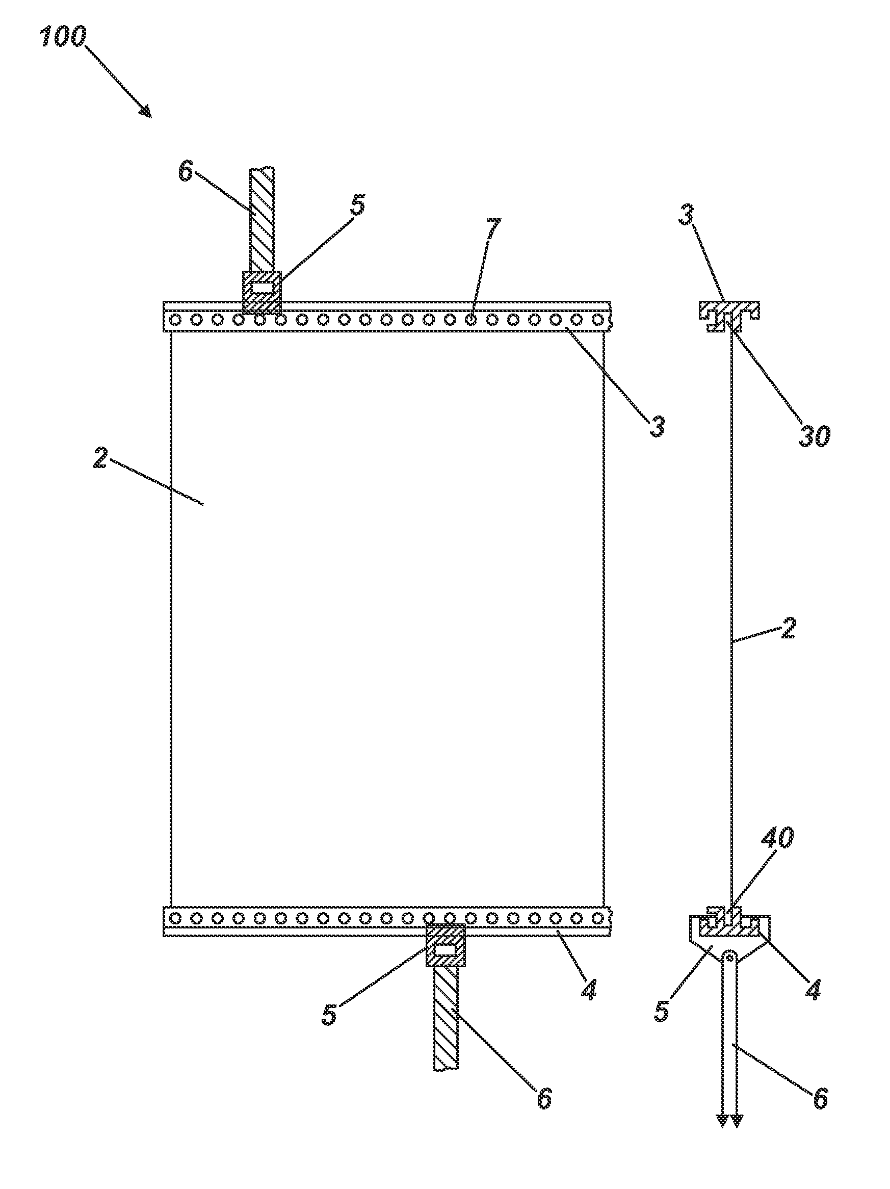
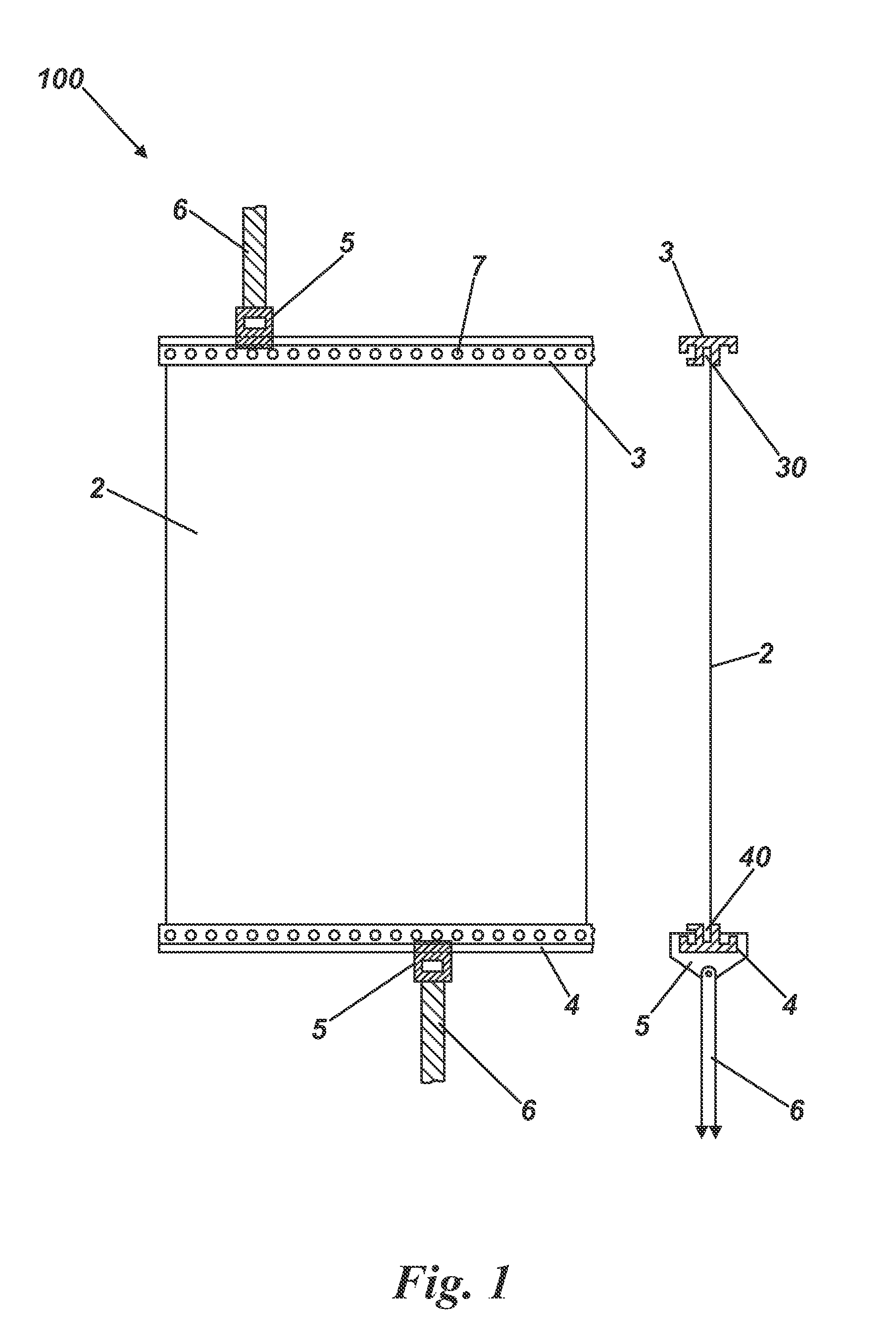
[0066]Referring first to FIG. 1, a projection apparatus shown generally as 100, comprises a polymeric projection screen 2, retention members 3, 4, tensioning brackets 5, tensioning straps 6 and a series of ultrasonic spot-welds 7. The screen 2 is shown as a foil and the retention members 3, 4 are each shown as an extruded or moulded plastic (e.g. PET) gripper bar although it will be appreciated that other means of construction could be envisaged.

[0067]In use, the screen 2 is inserted into the extruded channel 30, 40 of each of the retention members 3, 4 and then ultrasonically bonded to create the series of spot-welds 7. The ultrasonic bonding will be created by a portable ultrasonic welding device comprising an ultrasonic horn backed by a small hand-held anvil. The horn is attached via a cable to a high frequency ultrasonic generator capable of generating ultrasonic energy in the range of 20 to 40 kHz. Each spot weld may typically range from approximately 2 to 3 mm in diameter or g...


PUM

PropertyMeasurementUnit
Pressureaaaaaaaaaa
Lengthaaaaaaaaaa
Tensionaaaaaaaaaa

Abstract

Projection apparatuses and associated methods are provided. A representative apparatus includes: a support frame defining a projection area; a polymeric screen of sheet material sized and shaped to span at least a portion of the projection area; a retention member operative to contact the polymeric screen along an edge thereof; and a tensioning assembly operative to apply tension to the screen via the retention member, the tensioning assembly being operative to selectively reposition the retention member relative to the support frame.

Description

CROSS REFERENCE TO RELATED APPLICATIONS[0001]This application is a Continuation-in-Part application that claims priority to co-pending U.S. Utility patent application entitled, “Projection Screen and Method of Construction”, having Ser. No. 12 / 437,931, filed May 8, 2009, which claims priority to U.S. Provisional Patent Application entitled, “Projection Screen and Method of Construction”, having Ser. No. 61 / 051,397, filed May 8, 2008, both of which are entirely incorporated herein by reference.BACKGROUND[0002]1. Technical Field[0003]The invention relates to a projection screen and method. More particularly, but not exclusively, it relates to a projection screen retained by a retention member, and a method for constructing such a screen.[0004]2. Description of the Related Art[0005]The projection of an image upon a partially reflective and partially transparent screen such that it is observable by a viewer positioned in front of the screen is known as a “Pepper's ghost” arrangement fro...

Claims


Application Information

Patent Timeline
IPC IPC(8): G03B21/56
CPCB29C65/08Y10T29/49826B29C66/4722B29C66/71B29C66/7371B29C66/73713B29C66/82661B29L2031/3475G03B21/56G03B21/58G03B21/62B29C66/21B29C65/4895B29C65/48B29K2067/00B29C66/73711
Inventor HOWES, ALEXDAVIS, ADAM
Owner MUSION IP LTD
Why Eureka
Try Eureka