Circulating Fluidized Bed Combustor and a Method of Operating a Circulating Fluidized Bed Combustor

a fluidized bed and combustor technology, applied in the direction of lighting and heating apparatus, emission prevention, combustion types, etc., can solve the problems of large ash particles in the cfb system, high dust loading, etc., and achieve the effect of reducing the amount of pollutants in the atmospher

Inactive Publication Date: 2011-11-03
FOSTER WHEELER NORTH AMERICA CORP
View PDF13 Cites 17 Cited by
  • Summary
  • Abstract
  • Description
  • Claims
  • Application Information

AI Technical Summary

Benefits of technology

[0014]Another object of the present invention is to provide a circulating fluidized bed combustor that provides reduced amounts of pollutants to the atmosphere.
[0015]Yet ano

Problems solved by technology

It is produced when nitrogen in the fuel combines with the excess oxygen in the combustion air, and is only a problem with fuel containing fuel bound nitrogen.
Thus, resulting in larger ash pa

Method used


Image

  • Circulating Fluidized Bed Combustor and a Method of Operating a Circulating Fluidized Bed Combustor
  • Circulating Fluidized Bed Combustor and a Method of Operating a Circulating Fluidized Bed Combustor
  • Circulating Fluidized Bed Combustor and a Method of Operating a Circulating Fluidized Bed Combustor

Examples


Embodiment Construction

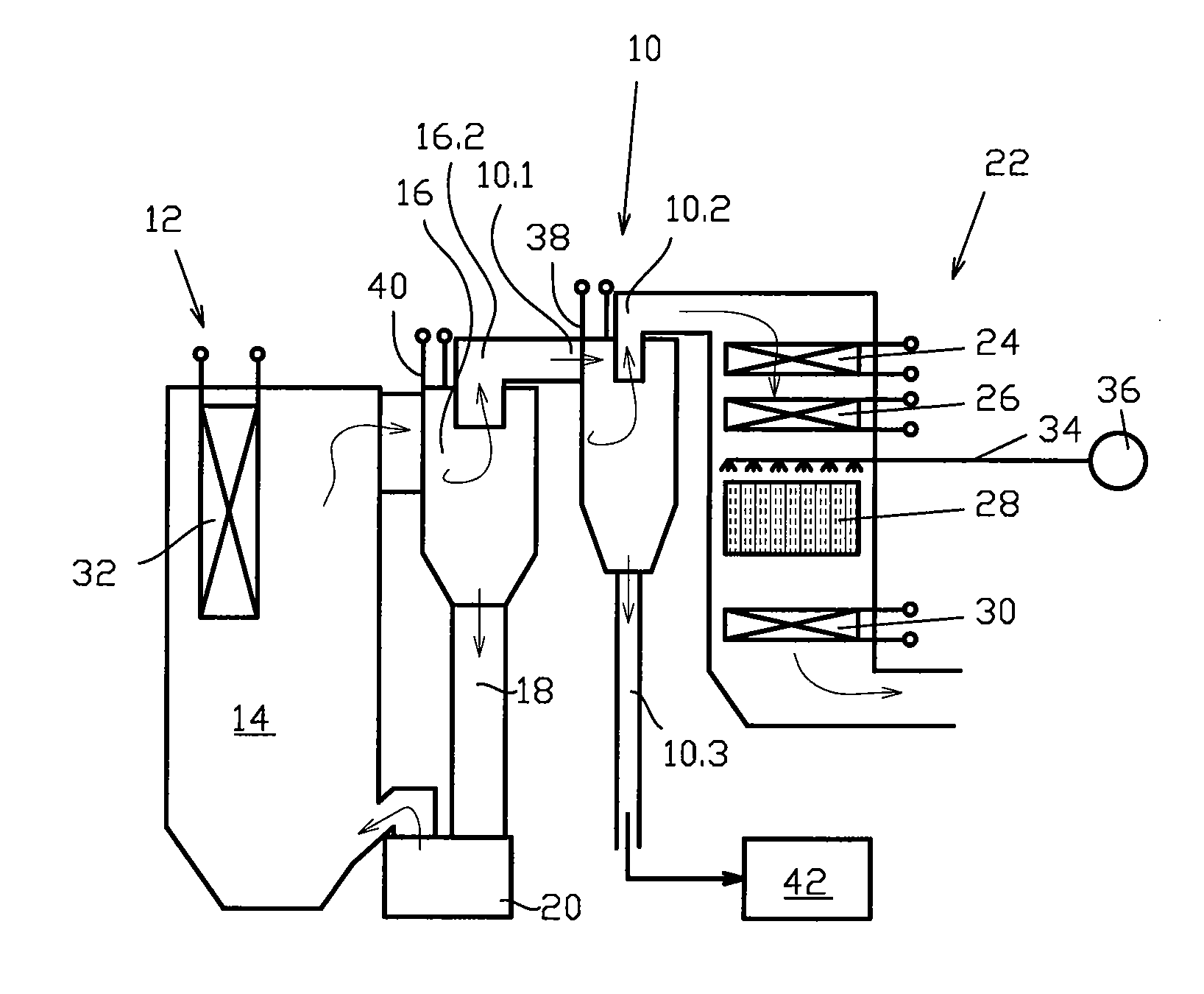
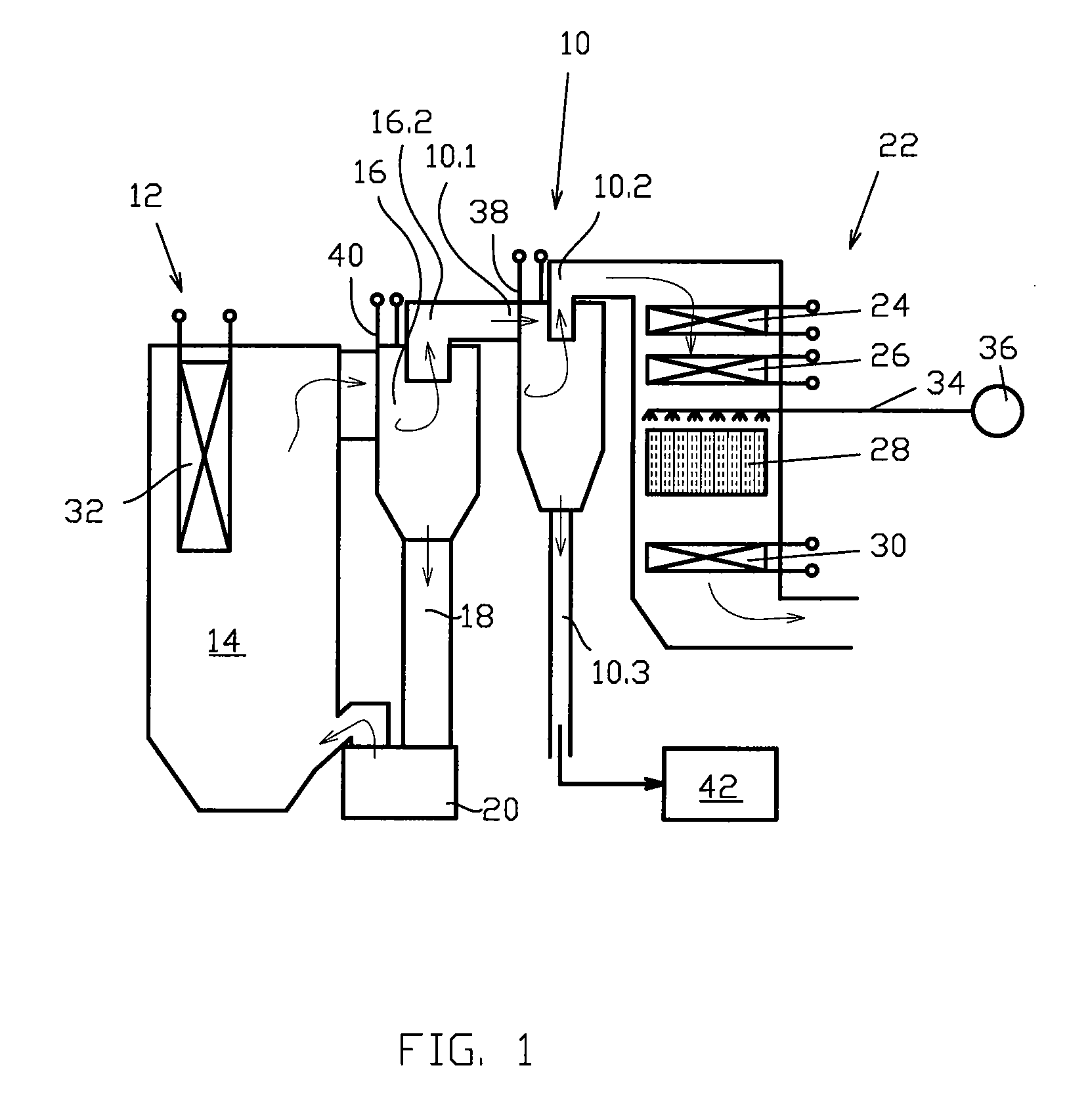
[0057]FIG. 1 schematically illustrates a circulating fluidized bed (CFB) combustor arrangement 10. The CFB combustor arrangement 10 comprises a circulating fluidized bed reactor 12 including a combustion chamber 14, in which fuel material may be combusted making use of a circulating bed of solid particles therein. The CFB reactor 12 is provided with numerous auxiliary devices, of which only those necessary for understanding the invention are described herein. The CFB reactor is connected at its upper portion to a cyclone separator arrangement 16, which acts as a primary separation stage. In the embodiment of FIG. 1, the cyclone separator arrangement 16 includes one cyclone separator, but, e.g., in larger CFB reactors, there may be several separators installed in parallel. The cyclone separator 16 is connected to the lower portion of the combustion chamber 14 via a return conduit 18, including a sealing device, like a loop seal, the purpose of which is, e.g., to prevent gas flow from...


PUM


Abstract

A circulating fluidized bed combustor arrangement includes (a) a circulating fluidized bed reactor in which (i) a combustion chamber combusts a fuel material in a suspension of solid particles of a circulating fluidized bed, (ii) a first cyclone separator arrangement receives a mixture of gases and solid particles from the combustion chamber for separating a first fraction of the solid particles from the exhaust gases, and (iii) a solid particle return system connected to the first cyclone separator returns separated solid particles to the combustion chamber, (b) a heat transfer section including a water/steam heat exchanger section arranged after the first cyclone separator arrangement in the exhaust gas flow path, (c) a heat recovery device provided in connection with the combustion chamber, the first cyclone separator arrangement and the heat transfer section being arranged for recovering heat resulting from the combustion process in the combustion chamber, (d) a selective catalytic reduction system arranged in the exhaust gas flow path, after the heat transfer section, for removing NOx from the exhaust gas, (e) a device for injecting NOx reducing agent into the exhaust gases upstream of the selective catalytic reduction system, and (f) a second cyclone separator arrangement provided downstream of the first cyclone separator arrangement and upstream of the heat transfer section, in which a second fraction of the solid particles is separated form the exhaust gases.

Description

TECHNICAL FIELD AND BACKGROUND OF THE INVENTION[0001]The present invention relates to a circulating fluidized bed combustor and a method of operating a circulating fluidized bed combustor. Further, it relates to a novel method of controlling NOx.[0002]A circulating fluidized bed combustor arrangement of the prior art comprises a furnace, to which fuel, bed material and combustion air are introduced. When combusting the fuel, heat is generated, and both ash and exhaust gases are formed. The exhaust gases are taken to a separator, which separates solid particles, including the bed material, from the gases, and returns the solid particles back to the furnace. It is distinctive to the combustion process that the oxidation reaction of the fuel material is intended to be as complete as possible. Thus, the flue gases or exhaust gases do not contain substantially any unburned material.[0003]Structurally, the circulating fluidized bed (CFB) combustor generally includes a furnace having a bot...

Claims


Application Information

Patent Timeline
IPC IPC(8): F23J15/02F23L7/00F23D1/00F23C10/08
CPCF23C10/002F23C10/10F23J15/003F23J2219/10F23J2215/10F23J2217/40F23J15/02
Inventor SELLAKUMAR, KUMARCIARLANTE, VICTORHACK, HORST
Owner FOSTER WHEELER NORTH AMERICA CORP
Why Eureka
Try Eureka