System and method for land application of waste fluids

a technology of waste fluid and system, applied in the field of land application of waste fluid, can solve the problems of difficult to exercise flow control, difficult to handle drilling mud, unsatisfactory environmental side effects, etc., and achieve the effect of high mapping accuracy results and more time-consuming and efficient technicians

Active Publication Date: 2011-11-03
SUMMIT LIABILITY SOLUTIONS
View PDF5 Cites 25 Cited by
  • Summary
  • Abstract
  • Description
  • Claims
  • Application Information

AI Technical Summary

Benefits of technology

[0017]Use of various of the embodiments disclosed herein will better effect compliance and costs associated therewith including avoiding spraying: in the wrong field, outside the appropriate area; in unacceptable proximity to identified water bodies and identified pipelines. Further, one avoids use of improper sloped terrain, overflow and excessive spray rates, and overlap of spraying. The disclosed embodiments control liquid discharge in accordance with assessed rules that ensure the above risks are eliminated. Further, using the annotated display provides the driver or operator with a form of night vision and steering assistance for field navigation and aesthetics. The drivers can focus on driving versus assessing fields and compliance matters. High mapping accuracy results and technicians can be more efficient, with more time focused on quality assessments and details.

Problems solved by technology

Drilling wells for oil and gas exploration invariably produces waste material.
However, excessive amounts of drill waste disposed within a given area of land, may lead to undesirable environmental side effects.
Drilling mud is a difficult fluid to handle.
Drill cuttings in the fluid make it difficult to exercise flow control, other than fully opening to allow fluid discharge or fully closing to disallow fluid discharge.
There are many problems with these current conventional practices.
During winter months, the technician scouting the land is often hampered by snow and uses, at best, dated aerial photographs for assessment.
Further, post spraying mapping may be impaired by rain, snow and agricultural activities, which may lead to inaccuracies in the reported data.
Trucks that discharge the drill waste fluid have no engineered environmental safeguards in place to ensure regulatory compliance.
As the truck operator is often among the least trained persons with regard to regulatory compliance requirements, reliance on the operator entails a high risk of non-compliance as a result of human error, weather conditions, poor visibility and the like.
Such known systems however, are aimed at improving efficiency and do not provide adequate safeguards to avoid overlap of zones on which fluids are dispensed, and require physical marker objects to be present on the target surface prior to applying the fluid.
The requirement for physical markings may be costly and may limit available candidate land surfaces for landspraying.
Moreover, the operation of known systems and methods does not take the slope of the terrain into account, which is a limiting factor for suitability for landspraying.

Method used


Image

  • System and method for land application of waste fluids
  • System and method for land application of waste fluids
  • System and method for land application of waste fluids

Examples


Embodiment Construction

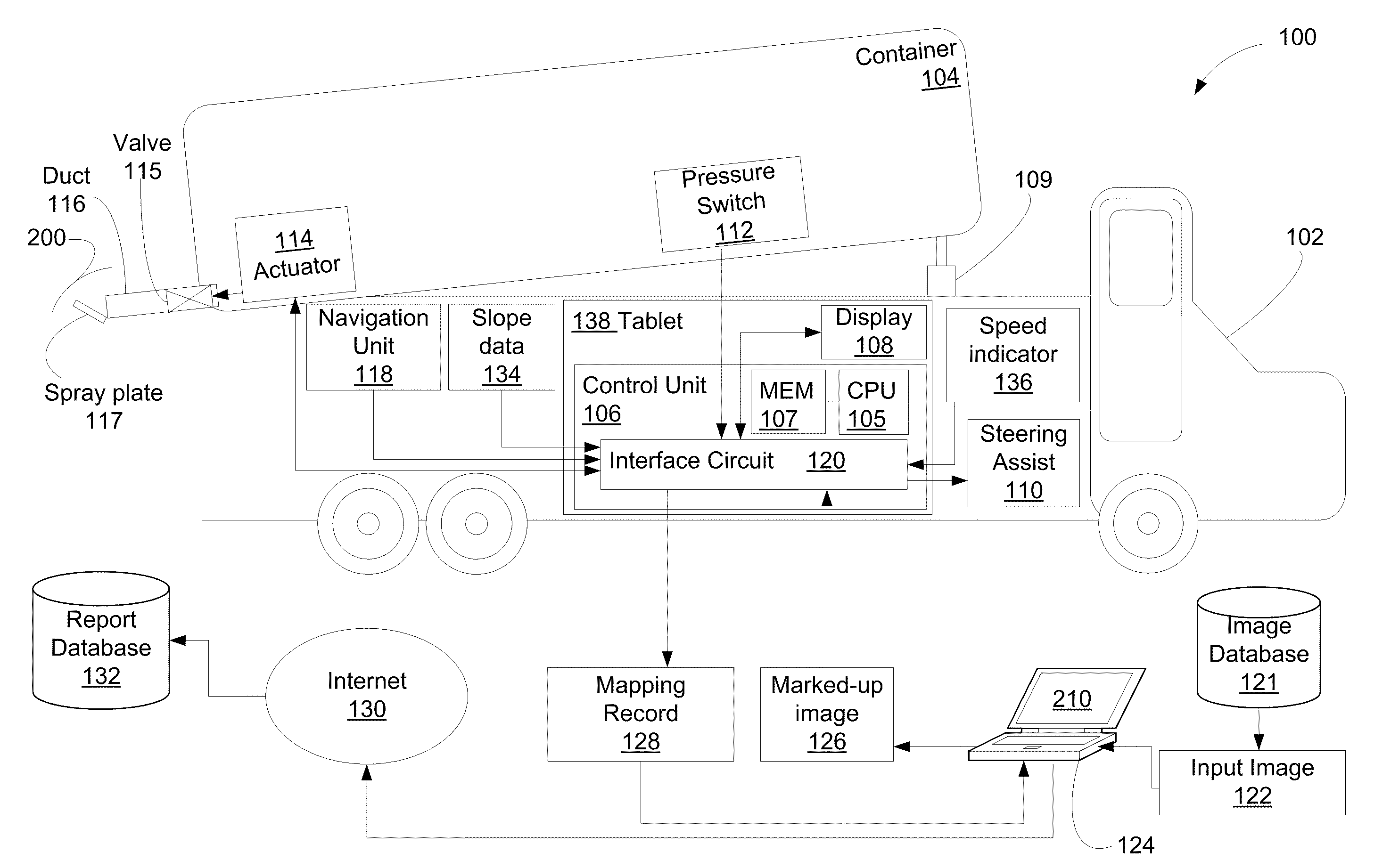
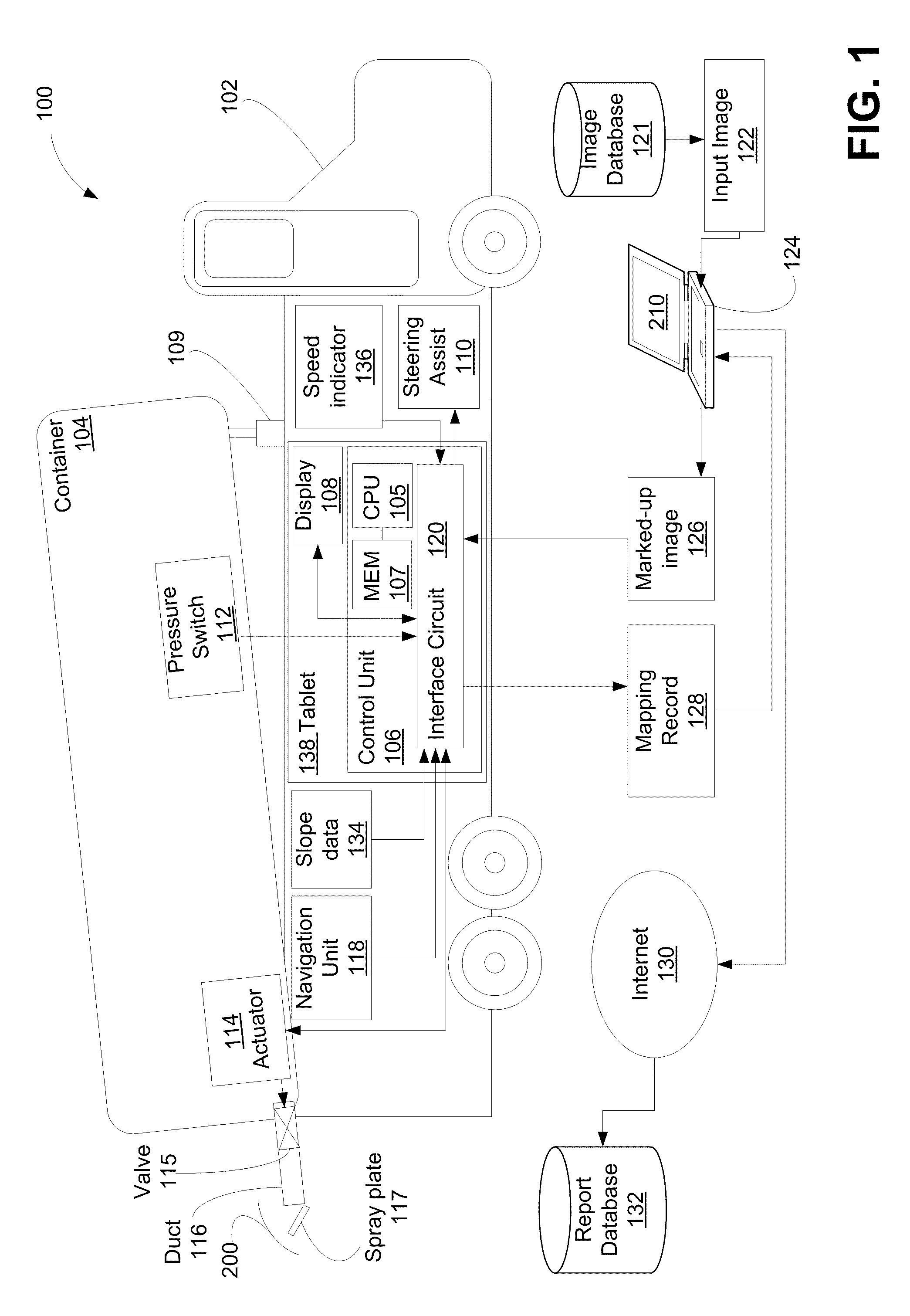
[0031]A system and control unit provide automated control and monitoring system for maximizing regulatory compliance in landspraying operations. While described herein in the context of landspraying of waste fluids such as drilling fluid, the apparatus and methods herein can be applied to the controlled deposition of other materials and waste fluids.

[0032]The control unit is typically installed in a vehicle having a fluid container mounted thereon. The container has a valve, operable by the control unit, to regulate discharge of waste fluid typically containing solid particle debris. The control unit obtains coordinate data for land surface to be sprayed, including boundaries of exclusion zones on the surface that should not be sprayed. The control unit then employs a navigation system and valve control to avoid spraying within the exclusion zones, to avoid overspraying in approved zones and to capture the exact mapping of deposited material for analysis and reporting.

[0033]The cont...


PUM


Abstract

A system and method are provided for automated control of application of fluid to a surface. A surface map is annotated with shapes designating zones for spraying, and excluding others. A control system in a vehicle uses the annotated map and GPS to assist the operator of the vehicle avoid spraying on excluded zones, and provides a record of the spraying operation including locations sprayed and fluid spray rates. The control system operates valves to control spraying from a container on the vehicle, based on several parameters, so as to avoid spraying excluded zones and steep slopes, to avoid overlaps, and to limit fluid spray rates below pre-determined maximums. The system further assists the operator by providing a visual guide on a display. A kit can be provided to retrofit a vehicle for landspraying.

Description

CROSS-REFERENCE TO RELATED APPLICATIONS[0001]This application claims the benefit of U.S. Provisional Application No. 61 / 330,236, filed Apr. 30, 2010.FIELD OF THE INVENTION[0002]The present invention relates to techniques for land application of waste streams generally and more particularly to controlling and monitoring the disposal or landspraying of drilling waste to comply with applicable government regulations.BACKGROUND OF THE INVENTION[0003]Drilling wells for oil and gas exploration invariably produces waste material. The drilling process typically involves the use rotary drill bits that are lubricated by drilling fluids sometimes called mud. As the drill bit grinds downward through soil and rock formation, large amounts of ground-up materials called drill cuttings and drilling fluids are generated, requiring environmentally safe disposal.[0004]Many methods exist for disposing drill waste. These include on-site disposal methods, off-site disposal methods, land-treatment methods...

Claims


Application Information

Patent Timeline
Patent Type & Authority Applications(United States)
IPC IPC(8): B05B12/00B05B15/06
CPCA01C23/001A01B79/005
Inventor ORCUTT, RUSSEL LLOYDPECHT, JASON
Owner SUMMIT LIABILITY SOLUTIONS
Why Eureka
Try Eureka