Apparatus and method for correcting susceptibility artefacts in a magnetic resonance image

Inactive Publication Date: 2015-12-17
UCL BUSINESS PLC
View PDF1 Cites 26 Cited by
  • Summary
  • Abstract
  • Description
  • Claims
  • Application Information

AI Technical Summary

Benefits of technology

[0033]Accordingly, the approach described herein helps to correct robustly and accurately for the geometric and intensity distortions in echo planar MRI images through field maps and image registration techniques. Field maps are prone to be noisy, especially at the interface of issue boundaries with different magnetic susceptibilities. Dynamic graph cuts may be used to find the most likely field map and uncertainty information associated with the generation of the field map. This estimated uncertainty associated with the generation of the field map may be used for a subsequent image registration step that is selectively driven in regions of high uncertainty. This approach supports an efficient computational implementation and is suitable for use in situations where (near) real-time susceptibility correction is required, such as for MR images acquired during a neuro-surgical procedure to support surgical navigation.
[0034]Accordin

Problems solved by technology

These inaccuracies can result in anatomical features being incorrectly located in an image, in other words, the positions of such features may be distorted from their true locations.
This distortion can be very significant, for example, in real-time MRI imaging for image-guided surgery, where it is extremely important to know the precise location of a medical instrument in respect to the different anatomical features—otherwise (for example) a treatment may be applied to the wrong location, or the medical instrument may inadvertently damage some other component of the body.
This new positioning is assumed to represent the correct (true) location of the anatomical feature corresponding to X. One drawback with this image intensity mapping is that it relies upon the image containing sharp (distinct), well-identified features.
However, if no (or only a few) such features are present in the image, for example, the image appears rather homogenous, then it is difficult to perform the desired registration and subsequent transformation.
A further drawback is that this method relies upon the availability of an existing undistorted image.
One difficulty with this approach is that the generating the field map uses the absolute or total phase, θT, whereas the MRI imaging only produces a residual phase θR, where θR=θT modulo(2π)

Method used


Image

  • Apparatus and method for correcting susceptibility artefacts in a magnetic resonance image
  • Apparatus and method for correcting susceptibility artefacts in a magnetic resonance image
  • Apparatus and method for correcting susceptibility artefacts in a magnetic resonance image

Examples


Embodiment Construction

1. Methods

A. Phase Modelling

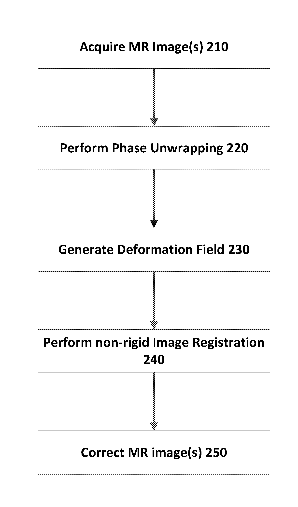
[0043]A known method for estimating the field map is to use the phase difference between two MR images acquired at different echo times. However, the phase images are uniquely defined only in the range of (−π, π] and hence the phase images need to be unwrapped at each voxel by an unknown integer multiple of 2π to obtain the true phase as in eq. (1).

φt(i)=φw(i)+2πni  (1)

where φt(i) is the true phase at a given voxel i, φw(i) is the wrapped phase and n is the unknown integer multiple of 2π that needs to be estimated. Phase unwrapping is an ill-posed problem and becomes intractable without regularization.

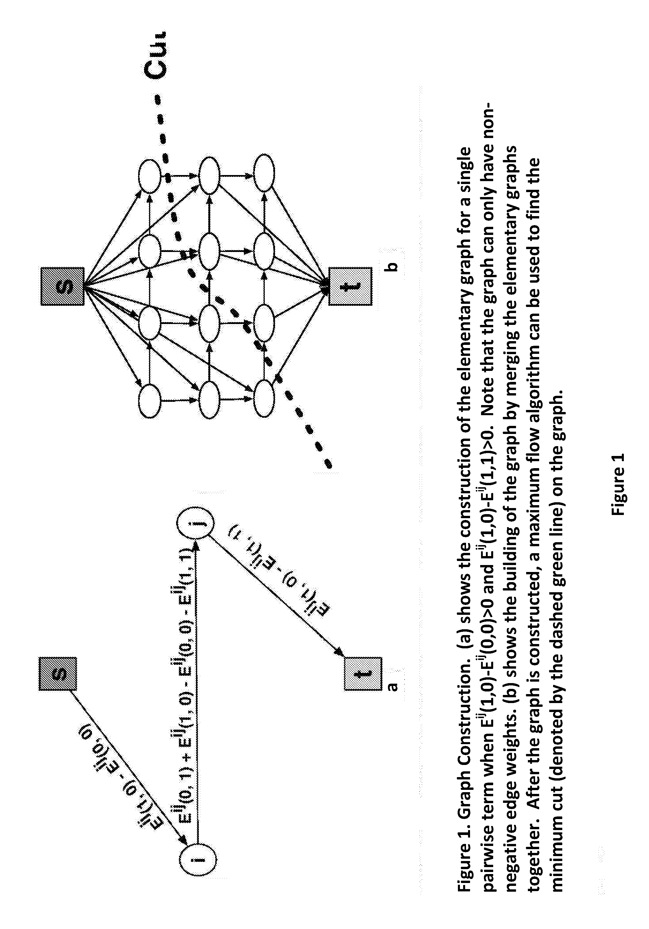
[0044]Similar to [18], the phase unwrapping method can be modelled as a Markov Random Field (MRF) where the true phase φ(t) and the wrapped phase φ(w) are modelled as random variables. We aim to find the discrete label set n(i) that gives the maximum a posteriori (MAP) estimate of the phase wraps:

φt(i)=maxP(φw|φt)LikelihoodP(φt)Prior(2)

The likelihood term in...


PUM


Abstract

An apparatus and method are provided for performing phase unwrapping for an acquired magnetic resonance (MR) image. The method includes modelling the MR phase in the MR image using a Markov random field (MRF) in which the true phase φ(t) and the wrapped phase φ(w) are modelled as random variables such that at voxel i of said MR image φ(t)(i)=φ(w)(i)+2πn(i), where n(i) is an unknown integer that needs to be estimated for each voxel i. The method further includes constructing a graph consisting of a set of vertices V and edges E and two special terminal vertices representing a source s and sink t, where there is a one-to-one correspondence between cuts on the graph and configurations of the MRF, a cut representing a partition of the vertices V into disjoint sets S and T such that sεS and tεT. The method further includes finding the minimum energy configuration, E(n(i)|φ(w)) of the MRF on the basis that the total cost of a given cut represents the energy of the corresponding MRF configuration, where the cost of a cut is the sum of all edges going from S to T across the cut boundary. The method further includes using the values of n(i) in the minimum energy configuration to perform the phase unwrapping from φ(w) to φ(t) for the MR image. A confidence may be computed for each voxel using dynamic graph cuts. The unwrapped phase from two MR images acquired at different times may be used to estimate a field map from the phase difference between the two MR images. The field map may be converted into a deformation field which is then used to initialise a non-rigid image registration of the acquired MR image against a reference image. The deformation field of the non-rigid registration is controlled to be smoother where the confidence is high.

Description

FIELD OF THE INVENTION[0001]The present invention relates to an apparatus and method for correcting susceptibility artefacts in magnetic resonance (MR) imaging, and to an apparatus and method for performing phase unwrapping of an MR image for use in such corrections.BACKGROUND OF THE INVENTION1. Introduction[0002]Magnetic resonance imaging (MRI) is widely used in medicine and other applications for performing three-dimensional imaging, for example of a human body (or part of a human body). In some cases, the MRI imaging may be performed in real-time to provide real-time (dynamic) visual feedback to a surgeon during a medical procedure, such as neuro-surgery.[0003]It is well-known that certain forms of MRI, such as echo planar imaging (EPI) are subject to susceptibility artefacts, inaccuracies in intensity and geometry caused by inhomogeneities in the magnetic field (sometimes referred to as B0 inhomogeneities). Such inhomogeneities may arise at the transition between two forms of ma...

Claims


Application Information

Patent Timeline
IPC IPC(8): G01R33/565G06T5/00G06T7/00G06K9/00G01R33/56G01R33/561
CPCG01R33/565G01R33/5608G01R33/5616G06T2207/10088G06T7/0024G06K9/00771G06T5/002G06T7/0014G01R33/24G01R33/56536G01R33/56545G06T7/30G06V20/52
Inventor OURSELIN, SEBASTIENDAGA, PANKAJ
Owner UCL BUSINESS PLC
Why Eureka
Try Eureka