Camera platform system and imaging system

a camera platform and imaging technology, applied in the field of imaging systems, can solve the problems of increasing the size and production cost of the apparatus, affecting the transmission of the apparatus, and limited the model of the lens that can be mounted in the remote control camera platform, so as to achieve the effect of simple structure, not easily affected, and accurate position information

Active Publication Date: 2011-11-03
CANON KK
View PDF5 Cites 26 Cited by
  • Summary
  • Abstract
  • Description
  • Claims
  • Application Information

AI Technical Summary

Benefits of technology

[0009]Accordingly, the present invention provides a remote control camera platform that has a simple structure without requiring a separate expensive position detection mechanism, is not re

Problems solved by technology

However, in the imaging system employing an encoder, the encoder is disposed on the side of the lens device, a position detection mechanism such as an encoding counter or the like needs to be provided separately on the side of the image forming system, resulting in an increase in the size and the production cost of the apparatus.
Also, when the imaging system is applied as a camera platform system, a lens to be mounted needs to have a position detection mechanism, and thus, the model of a lens that can be mounted in a remote control camera platform is limited.
On the other hand, in the apparatus that takes into account the delay factor of the drive units of the remote control camera platform, such an apparatus would be greatly affected by transmission delay when a long distance between the operation device and the remote control camera platform exists in the case of, for example, golf broadcast or when the apparatus is adopted into a system that is connecte

Method used


Image

  • Camera platform system and imaging system
  • Camera platform system and imaging system
  • Camera platform system and imaging system

Examples


first embodiment

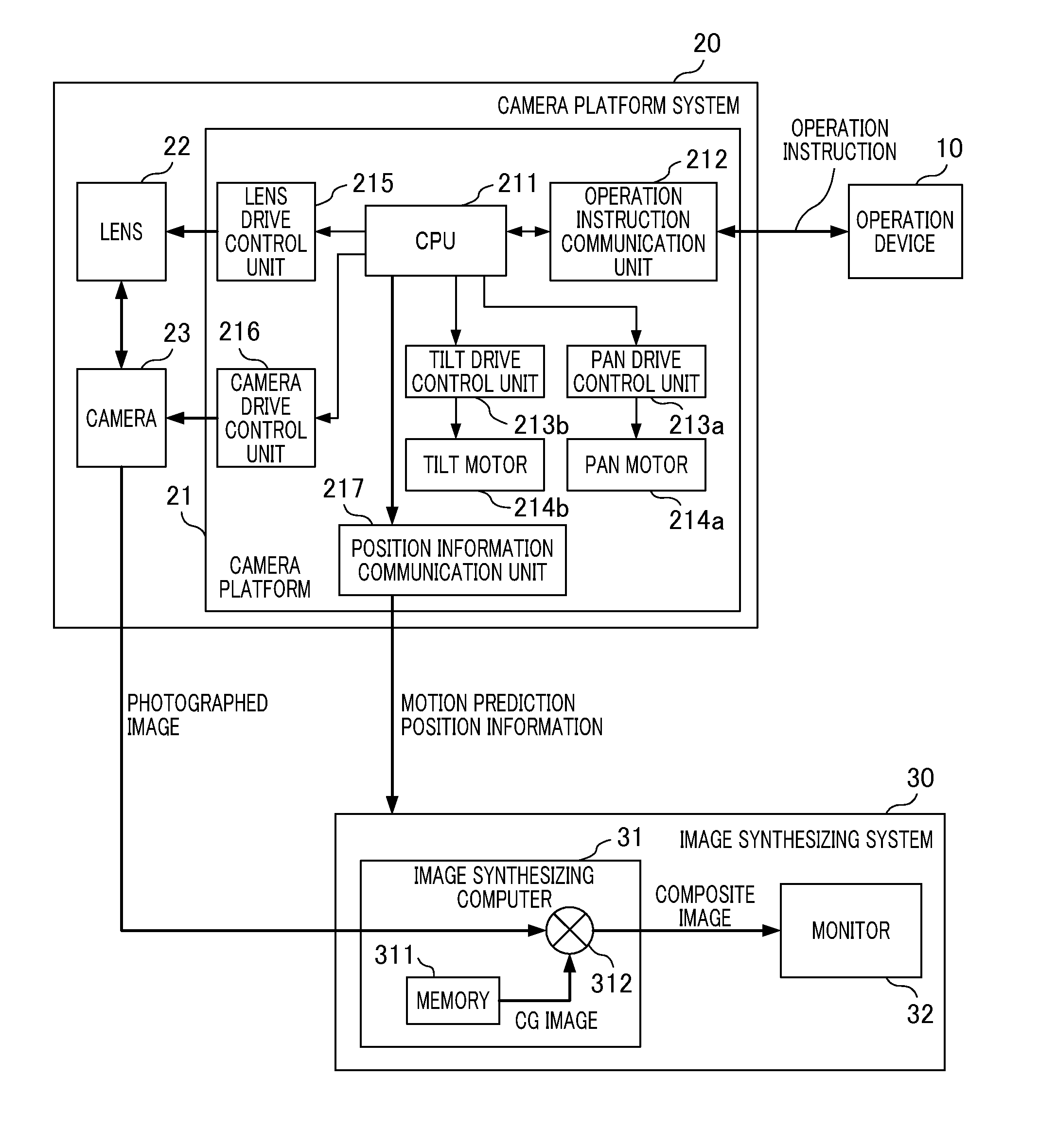
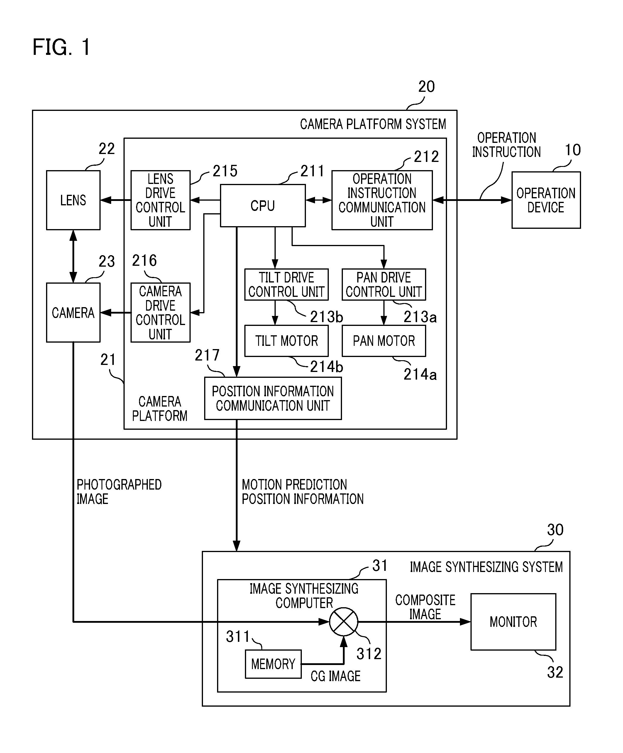
[0031]First, the configuration of an imaging system according to a first embodiment of the present invention will be described with reference to FIG. 1. FIG. 1 is a block diagram illustrating the configuration of an imaging system according to a first embodiment of the present invention. In FIG. 1, the imaging system of the present embodiment is constituted by an operation device 10, a camera platform system 20, and an image synthesizing system 30. An operator operates the operation device 10, and remotely operates the camera platform system 20 to thereby adjust zoom / focus / tilt / pan and various functions of a camera, whereby a desired image can be acquired. A photographed image acquired by the camera platform system 20 is synthesized with a CG image using the image synthesizing system 30.

[0032]The camera platform system 20 is constituted by a camera platform 21, a lens 22, and a camera 23. The camera platform 21 is constituted by a CPU 211, an operation instruction communication unit...

second embodiment

[0039]FIG. 5 is a block diagram illustrating the configuration of an imaging system according to a second embodiment of the present invention. The second embodiment (FIG. 5) differs from the first embodiment (FIG. 1) in that bi-directional communication can be established between the CPU 211 and the lens drive control unit 215 and between the lens drive control unit 215 and the lens 22. The same elements as those shown in the first embodiment are designated by the same reference numerals, and no further description will be given here. Hereinafter, the flow of processing performed by the CPU 211 up until position information about the lens 22 is transmitted to the image synthesizing system 30 will be described with reference to the flowchart shown in FIG. 6.

[0040]The CPU 211 performs lens model recognition processing for recognizing the model of the lens 22 in the lens drive control unit (lens model recognition unit) 215, and stores information regarding the model (step S11). Informa...

third embodiment

[0046]FIG. 7 is a block diagram illustrating the configuration of an imaging system according to a third embodiment of the present invention. The third embodiment (FIG. 7) differs from the first embodiment (FIG. 1) in that the position information communication unit 217 eliminated, and a position signal superimposition unit 218 is added. The same elements as those shown in the first embodiment are designated by the same reference numerals, and no further description will be given here.

[0047]The position signal superimposition unit 218 superimposes the motion prediction position information acquired as in the first embodiment on the image signal from the camera 23. For example, a blanking area of an HD-SDI (High Definition television-Serial Digital Interface) signal may be employed. More specifically, motion prediction position information is embedded in the blanking area of an HD-SDI signal, whereby the motion prediction position information on the photographed image acquired at a g...


PUM


Abstract

The camera platform system of the present invention operates at least one function selected from zoom/focus/tilt/pan/iris of a mounted camera or lens in response to an operation instruction output from an operation device. The camera platform system includes a drive control unit configured to convert an operation instruction output from the operation device into a drive control signal corresponding to any one motion of the zoom/focus/tilt/pan/iris; a motion prediction position calculation unit configured to calculate a motion prediction position of any one of the zoom/focus/tilt/pan/iris based on the drive control signal converted by the drive control unit; and a motion prediction position output unit configured to output the motion prediction position, which has been calculated by the motion prediction position calculation unit, as motion prediction position information.

Description

BACKGROUND OF THE INVENTION[0001]1. Field of the Invention[0002]The present invention relates to an imaging system, and in particular, relates to a camera platform system that can remotely drive a zoom / focus / tilt / pan and the like.[0003]2. Description of the Related Art[0004]Conventionally, an imaging system (virtual studio system) for acquiring a composite image in which a photographed image is synthesized with a computer graphic (hereinafter referred to as “CG”) image is well known. In the virtual studio system, a CG image, which is the background (or foreground) of a photographed image, needs to be changed in accordance with the motion of the photographed image. A camera serving as an imaging apparatus for obtaining a photographed image is mounted on a remote control camera platform that remotely controls panning for rotating the direction of the camera in the left and right direction, or tilting for rotating the direction of the camera in the up-and-down direction (pan / tilt), and...

Claims


Application Information

Patent Timeline
IPC IPC(8): H04N5/232
CPCG03B3/10G03B3/12H04N5/232H04N5/222G03B13/36H04N23/695
Inventor KAGEI, KENJI
Owner CANON KK
Why Eureka
Try Eureka