Light source

a technology of light source and diode, which is applied in the direction of instruments, lighting and heating equipment, fibre light guides, etc., can solve the problems of incandescent light source life span typically relatively short, and the danger of burning objects that come into contact with glass bulbs, so as to achieve the effect of eliminating or reducing the problem

Active Publication Date: 2011-11-03
SIGNIFY HLDG BV
View PDF6 Cites 42 Cited by
  • Summary
  • Abstract
  • Description
  • Claims
  • Application Information

AI Technical Summary

Benefits of technology

In view of the above, it is an object of the present invention to provide a light source that alleviates or eliminates the problems as described above.
According to yet another embodiment of the present invention, the light source further includes a base onto which the light unit is arranged, which base includes an electrical connector arranged to mate with a socket connector of a luminaire or light fixture. The base further includes electrical circuitry connected to the electrical connector, which electrical circuitry is arranged to receive electrical power from the electrical connector and, by means of the electrical power, operate the light unit. In this manner, an easy fitting of the light source into a light fixture or luminaire normally employing an incandescent light source is achieved. The light source may further include a heatsink device arranged in the base, which heatsink device is adapted to dissipate heat generated by the light unit. Thus, the surfaces of the light source can be kept relatively cool to avoid burns to a user caused by contact with the light source. Furthermore, the life span of the light source can be increased due to less thermal stress and / or strain in the light source components.

Problems solved by technology

However, the life span of incandescent light sources is typically relatively short, usually limited to the life span of the filament.
In addition, the glass bulb generally becomes very hot due to the high temperature of the filament, presenting a potential danger of burning objects that come into contact with the glass bulb.
However, most LEDs are only capable of emitting light into a hemisphere (solid angle 2π sr), whereas incandescent light sources employing a glowing filament generally emit light uniformly into a full sphere (solid angle 4π sr).

Method used


Image

  • Light source
  • Light source
  • Light source

Examples


Embodiment Construction

Different exemplary embodiments of the present invention will now be described mainly with respect to a light source being arranged for retrofitting into a luminaire normally employing an incandescent light source. However, it is to be understood that the light source is not limited to the exemplary case of retrofitting applications, but may rather be a light source used in a variety of applications.

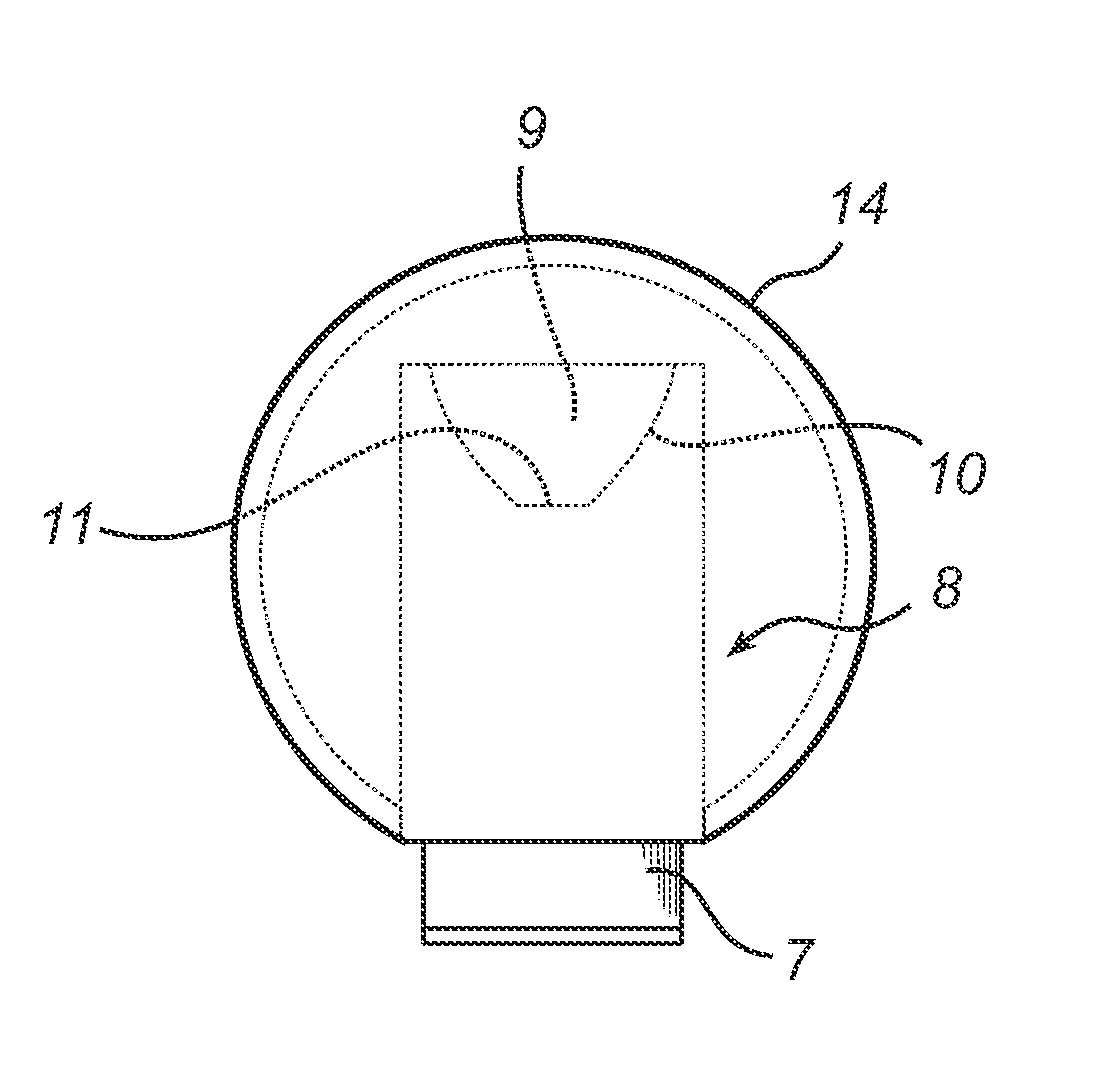
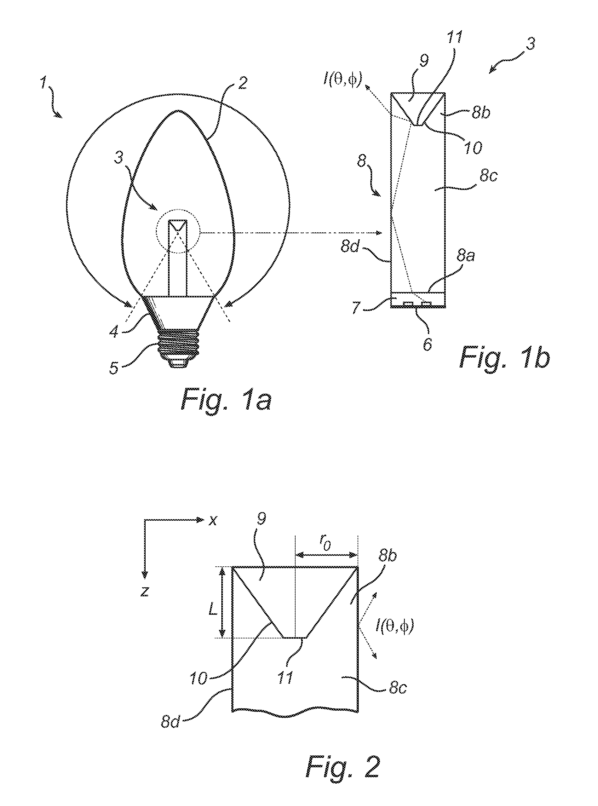
FIG. 1a is a schematic sectional view of a light source 1 illustrating an exemplary embodiment of the present invention, the light source 1 being arranged for retrofitting into a luminaire (not shown) normally employing an incandescent light source, such as a filamented light bulb. Such a luminaire may also be a halogen lamp or the like. It is to be understood that in the context of the present invention, by the term “retrofitting” it is meant fitting into a light fixture normally used for incandescent light sources (that is, replacing an incandescent light source normally used in the lu...


PUM


Abstract

The present invention relates to a light emitting diode, LED, light source that may be arranged for retrofitting into a luminaire employing an incandescent light source. The light source comprises a light guide into which light from one or more LEDs in a light unit arranged at one end of the light guide is injected, and a reflector having a reflecting surface arranged at the other end of the light guide and facing towards the light guide capable of reflecting light incident on the reflecting surface. According to the present invention, the reflector comprises at least one transmitting portion being arranged such that at least a portion of light incident on the at least one transmitting portion is transmitted through the reflector, for example a through hole extending along an axis, allowing for an almost viewing angle independent light intensity of the light source.

Description

FIELD OF THE INVENTIONThe present invention generally relates to the field of lighting design. In particular, the present invention relates to a light emitting diode (LED) light source, which may be arranged for retrofitting in luminaires employing incandescent light sources, such as light bulbs.BACKGROUND OF THE INVENTIONConventional incandescent light sources generally convert an electrical current to light by applying a current to a filament, typically made of tungsten, which causes the filament to glow. The filament is generally suspended near the center of a glass bulb, thereby providing radial distribution of light that can be used to illuminate, e.g., a room. Such conventional incandescent light sources are typically used in chandeliers. Due to the high brightness of the glowing filament (˜1 Mcd / m2), crystals in the chandelier exhibit decorative sparkling light effects. However, the life span of incandescent light sources is typically relatively short, usually limited to the ...

Claims


Application Information

Patent Timeline
Patent Type & Authority Applications(United States)
IPC IPC(8): H01L33/02
CPCF21K9/52F21V7/0091F21Y2101/02G02B6/001G02B17/004F21K9/56G02B27/0994G02B19/0066G02B19/0028F21K9/135F21K9/54G02B17/0856F21K9/232F21K9/61F21K9/62F21K9/64F21Y2115/10
Inventor BOONEKAMP, ERIKDUESTER, THOMAS
Owner SIGNIFY HLDG BV
Why Eureka
Try Eureka