
Radiation structure without light guiding board

a radiation structure and light guiding technology, applied in shaving accessories, lighting and heating apparatuses, instruments, etc., can solve the problems of reducing the efficiency of emitting, and consuming energy, so as to reduce the thickness and weight, and promote the illumination of the radiation structure. , the effect of high directivity

Active Publication Date: 2011-11-03
SOUTHERN TAIWAN UNIVERSITY OF TECHNOLOGY
View PDF3 Cites 33 Cited by
  • Summary
  • Abstract
  • Description
  • Claims
  • Application Information

AI Technical Summary

Benefits of technology

Accordingly, the present invention achieves the following advantages:1. The radiation structure without a light guiding board adapts to reduce the thickness and weight.2. The notches in an irregular shape or a V-shape formed on the rising surface of the optical plate allow the streams of light to achieve a more even reflection and scattering, so that the illumination of the radiating surface would be more consistent, and the illumination of the radiation structure could be further promoted.3. Since the radiant half-intensity angles of the light sources are defined below 15 degrees, the light source is able to possess the high directivity. Moreover, due to the fact that the optical axial directions of the light sources face to the rising surface of the rising area on the optical plate, most light are projected onto the optical plate, so that the large amount of light extensively scattered from the diffusion plate would more preferably enhance the radiance thereof.

Problems solved by technology

Nonetheless, after the light source passing through the light guiding board, certain consumption of energy would lower the emitting efficiency.
Especially, in view of the consumption, most side-edged backlight modules in a medium size could merely provide the emitting efficiency less than 70%, and the backlight module adapted to monitors even adversely provides the emitting efficiency just a bit higher than 50%.
Additionally, if no optical element is employed to guide the projection of the streams of light, the occurrence of the brighter two sides with a darker middle section would be adversely resulted.

Method used


Image

  • Radiation structure without light guiding board
  • Radiation structure without light guiding board
  • Radiation structure without light guiding board

Examples


Embodiment Construction

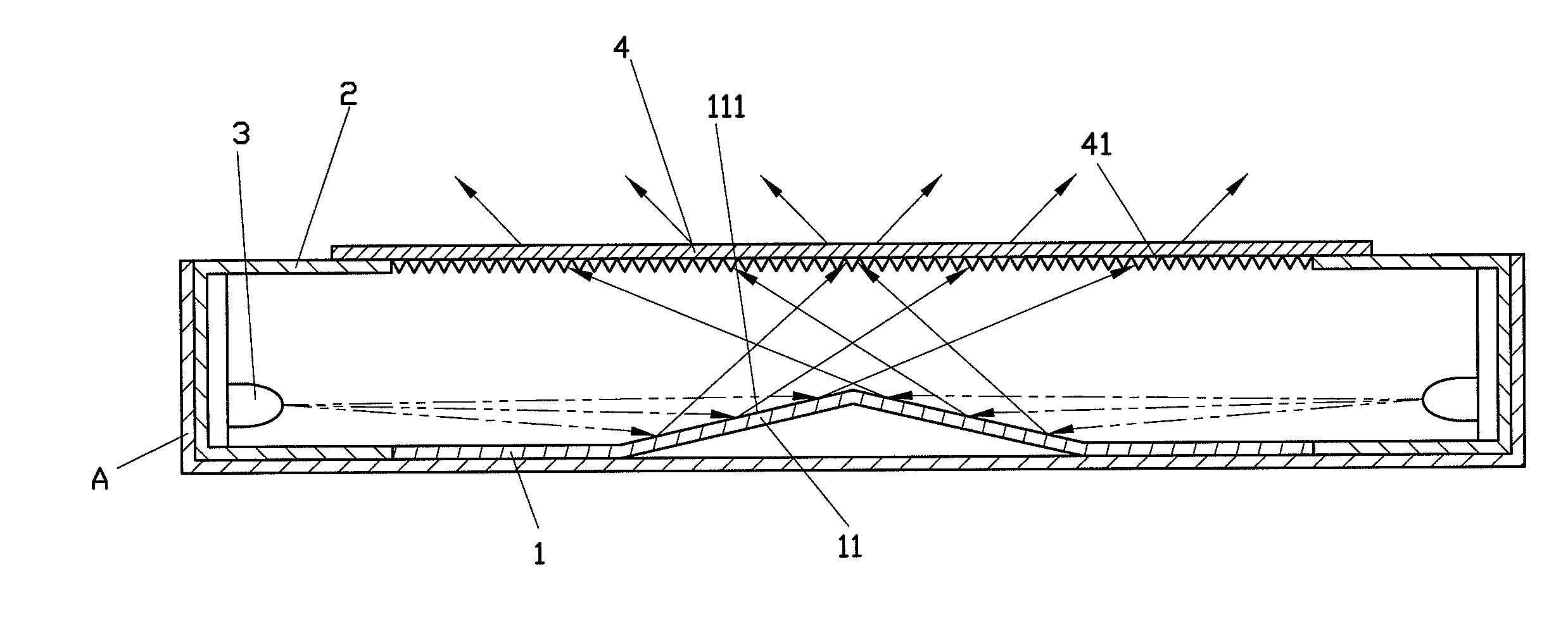
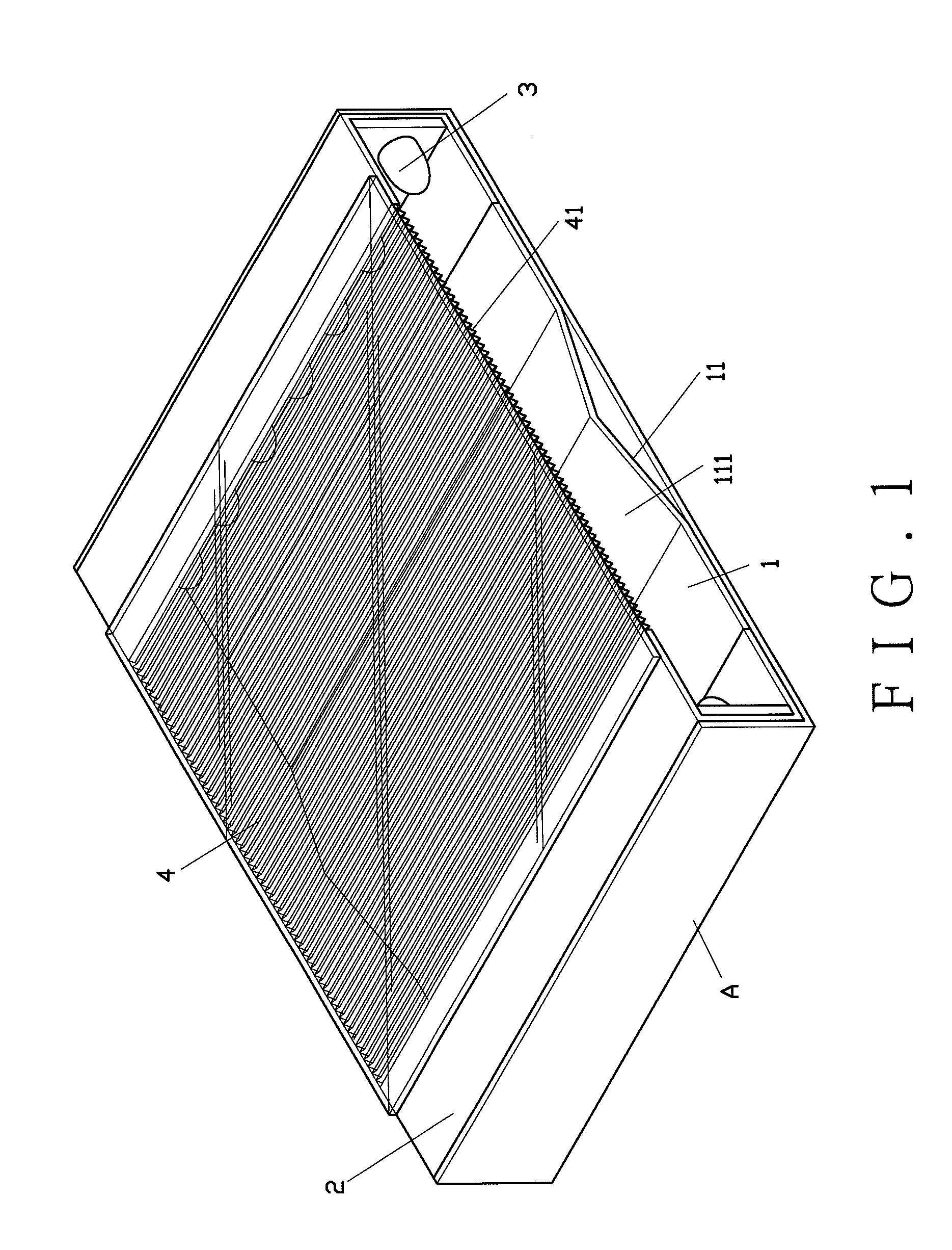
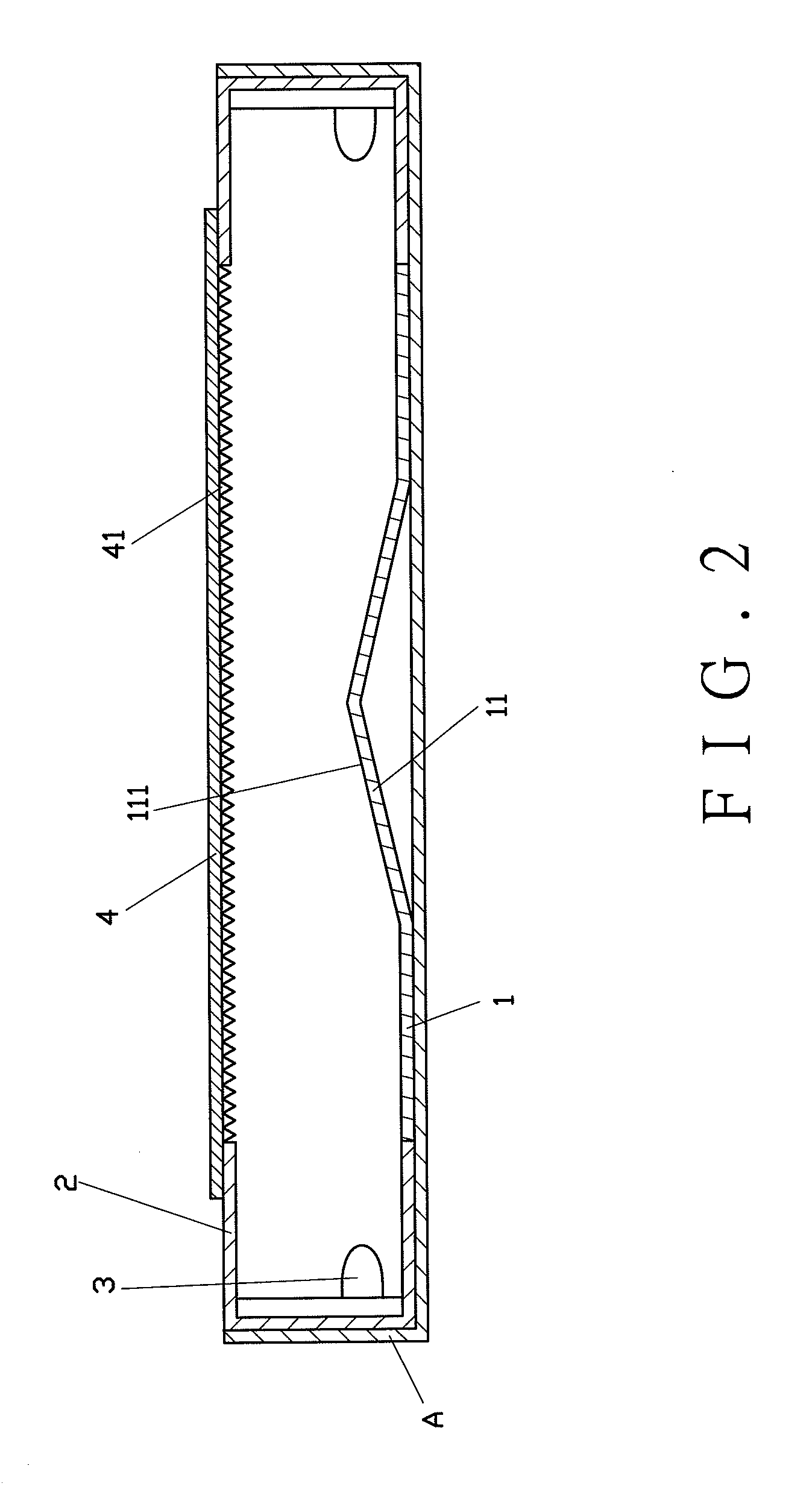
Referring to FIGS. 1 and 2, a radiation structure without a light guiding board of the present invention would cooperate with a frame (A), and comprises an optical plate (1), two reflecting housings (2), two light sources (3) and a diffusion plate (4).

The optical plate (1) includes at least one rising area (11) disposed thereon. The rising area (11) is formed by a rising surface (111). The reflecting housings (2) are connected to two sides of the optical plate (1). The light sources (3) adopting LED tubes are disposed close to the two sides of the optical plate (1). Wherein, radiant half-intensity angles of the two light sources (3) are defined below 15 degrees. As it should be, the preferable performance of the radiant half-intensity angles are defined between 5 degrees and 15 degrees. Additionally, the two light sources (3) are contributed to form respective optic axial directions (31) that face to the rising surface (111). As shown in FIGS. 3 and 4, the two light sources (3) emit...


PUM


Abstract

A radiation structure without a light guiding board for a backlight module or an illuminant device includes an optical plate formed with at least one rising area having a rising surface defined at the center thereof, two light sources disposed adjacent to two sides of the optical plate, and a diffusion plate. The light sources each possess a radiant half-intensity angle below 15 degrees for respectively forming optic axial directions thereof, allowing a radiation field to be diffusively formed from the pivoting of the optic axial directions. Whereby, the optic axial directions respectively face toward the rising surface, allowing the projection of the radiation field on the rising surface, and the diffusion plate is disposed above the rising area of the optical plate. Therefore, an even radiating surface caused by a diffusion of the light sources from the diffusion plate could be preferably obtained even if no light guiding board is applied.

Description

BACKGROUND OF THE INVENTION1. Field of the InventionThe present invention relates to a radiation structure without a light guiding board, especially to a radiating surface that achieves an even scattering from a diffusion plate even if the guiding board is not used in a backlight module or the like.2. Description of the Related ArtA conventional backlight module for a liquid crystal display disclosed in Taiwan patent published number 200825553, “A BACKLIGHT MODULE”. The referred backlight module comprises at least one light guiding board, at least one light source disposed at one side of the light guiding board, a diffusion plate mounted above the guiding board, not contacting the guiding board, and a mixing cavity defined between the light guiding board and the diffusion plate. Whereby, the streams of light emitted from an emission plane of the light guiding board would be adequately mixed in the mixing cavity, thence allowing the light to be emitted via the diffusion plate toward ...

Claims


Application Information

Patent Timeline
IPC IPC(8): F21V7/04
CPCG02B6/0096G02B6/0053G02B6/0046G02F1/133615
Inventor KANG, CHIH-CHIEHLIN, JENG-FENGWU, YU-CHANGYU, CHUN-XIANCHEN, TAI-JUNGCHUANG, SHAO-TUN
Owner SOUTHERN TAIWAN UNIVERSITY OF TECHNOLOGY
Features
  • Generate Ideas
  • Intellectual Property
  • Life Sciences
  • Materials
  • Tech Scout
  • Unparalleled Data Quality
  • Higher Quality Content
  • 60% Fewer Hallucinations
Learn More