
Remote management system for self-organizing femtocells

Inactive Publication Date: 2011-11-03
JUNI KOREA CO LTD
View PDF9 Cites 39 Cited by
  • Summary
  • Abstract
  • Description
  • Claims
  • Application Information

AI Technical Summary

Benefits of technology

[0006]The present disclosure is directed to an optimization method for radio parameters that reduces the exhaustive search at the femtocell level and also finds near optimal radio parameters for balanced cell coverage and cell capacity, minimizing interference between different cells.
[0010]Various algorithms with different objectives should be incorporated. Various objectives for the RMS include: continuous, optimized, and matched UL and DL coverage, optimized DL and UL capacity of the system, balanced trade-off between coverage and capacity, interference reduction, controlled cell edge performance, minimized human intervention in network management and optimization tasks, and energy savings.
[0011]The present disclosure provides a method of a centralized sequential frequency assignment that uses both radio scanning results from a femtocell and location information. The method minimizes the interference power and maximizes the receiver SINR (signal to interference ratio) for all mobile stations in order to maximize capacity of each femtocell. Also, an optimal preamble index is decided in similar fashion.
[0012]Even though the method is a centralized method and the RMS makes major decisions, each femtocell may help the RMS make an optimal decision by transferring more accurate radio scanning information, such as RSSI from nearby femtocells and frequency assignment for each femtocell.

Problems solved by technology

Moreover, some closed subscriber group (CSG) femtocells will not allow a MS that is not registered to the femto BS and some open subscriber group (OSG) femtocells will allow any MS to be connected or handed over from macro cells.

Method used


Image

  • Remote management system for self-organizing femtocells
  • Remote management system for self-organizing femtocells
  • Remote management system for self-organizing femtocells

Examples


Embodiment Construction

[0027]In the following description, certain specific details are set forth in order to provide a thorough understanding of various disclosed embodiments. However, one skilled in the relevant art will recognize that embodiments may be practiced without one or more of these specific details, or with other methods, components, materials, etc. In other instances, well-known structures or components or both associated with remote communication devices and remote management systems, including but not limited to remote radio access point devices and remote management stations, have not been shown or described in order to avoid unnecessarily obscuring descriptions of the embodiments.

[0028]Unless the context requires otherwise, throughout the specification and claims that follow, the word “comprise” and variations thereof, such as “comprises” and “comprising” are to be construed in an open inclusive sense, that is, as “including, but not limited to.” The foregoing applies equally to the word...


PUM


Abstract

A method for initialization of a remote femto base station by a remote management system in a radio access network, the method comprising: powering on the femto base station; transmitting an initial configuration file from the remote management system to the femto base station; initializing the femto base station with the initial configuration file; scanning neighbor femto base stations; transmitting the results of the scanning of neighbor femto base stations and transmitting the femto base station location information to the remote management system; the remote management system setting a neighbor list and radio frequency parameters in response to receipt of the transmission from the femto base station; generating an updated configuration file based on the generated neighbor list and radio frequency parameters; transmitting the updated configuration file to the femto base station; and applying the updated configuration file at the femto base station and starting operation.

Description

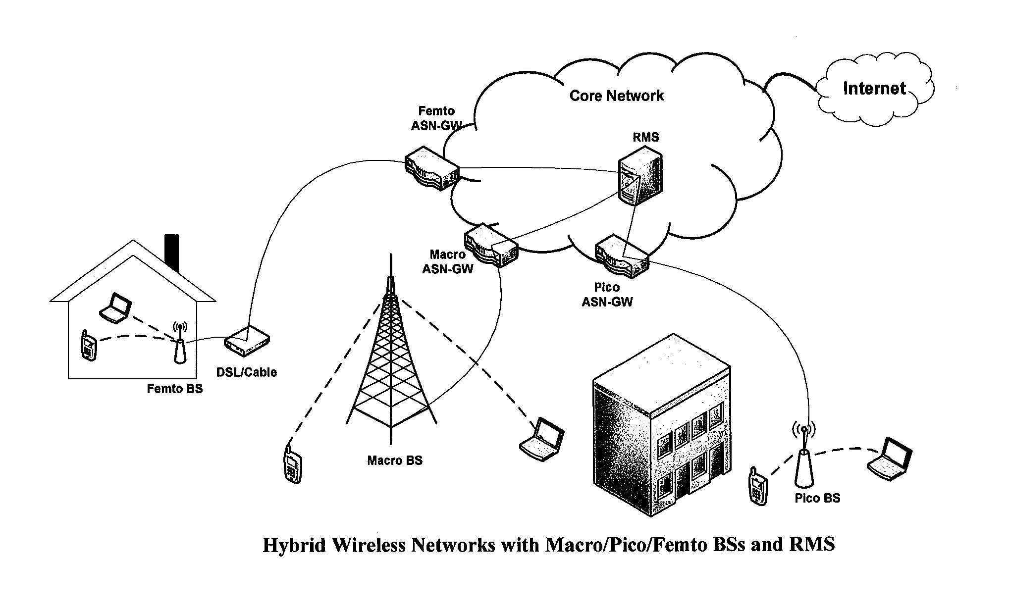
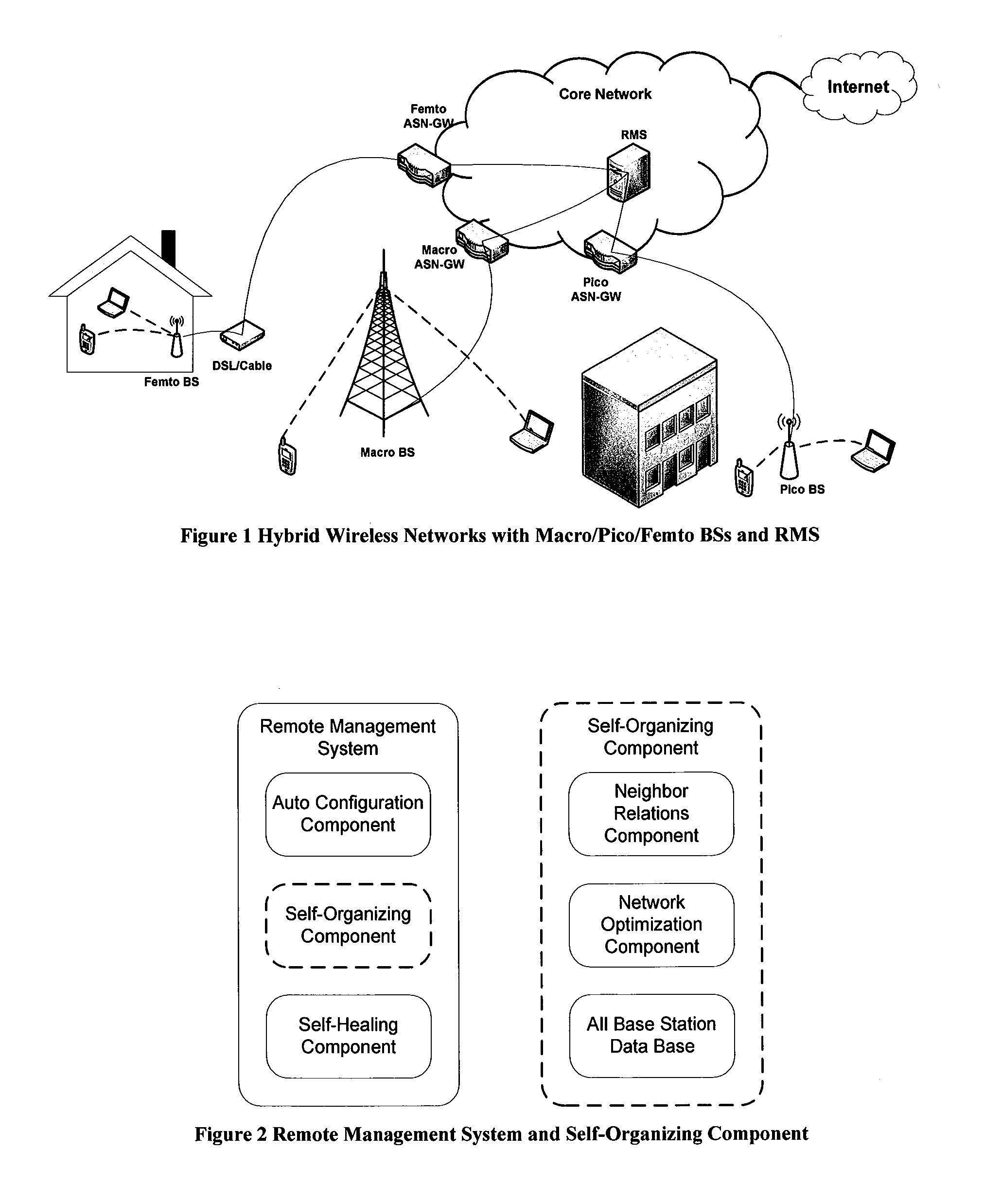
BACKGROUND[0001]1. Technical Field[0002]The present disclosure relates to remote management of femtocells in hybrid wireless networks, which include macro cells, pico cells and femtocells with CSG and OSG.[0003]2. Description of the Related Art[0004]Service providers are preparing for mass deployment of broadband wireless systems, such as, Mobile WiMAX or LTE (long-term evolution). In urban areas, macro base stations (BS) may cover a large area, but due to penetration loss and shadings from buildings, plural pico BSs and femto BSs need to be deployed. FIG. 1 shows an example of a hybrid wireless network that includes macro, pico and femto BSs altogether. Hereafter, we call areas covered by macro BS, pico BS and femto BS as macro cell, pico cell and femtocell, respectively. Even though FIG. 1 shows a Remote Management System (RMS) controlling the femtocells, pico cells and macro cells, the environment for the proposed method can be femtocells only, or pico cells only, or macro cells ...

Claims


Application Information

Patent Timeline
IPC IPC(8): H04W8/00
CPCH04W24/00H04W28/04H04W28/18H04W84/18H04W48/16H04W84/045H04W36/0061H04W24/04H04W16/10H04W16/32
Inventor YUN, JUNGNAMPARK, KEUN RYOLPARK, SEONG DONGHUR, YERANG
Owner JUNI KOREA CO LTD
Learn More