

Decomposition with multiple exposures in a process window based opc flow using tolerance bands
a technology of tolerance bands and process windows, applied in the field of design automation, can solve the problems of significant challenges to the patterning process, inability to ensure adequate, and inability to independently control the ret techniques, so as to achieve a well balanced retargeting allowance and avoid pattern failure.
- Summary
- Abstract
- Description
- Claims
- Application Information
AI Technical Summary
Benefits of technology
Problems solved by technology
Method used
Image

Examples
Embodiment Construction
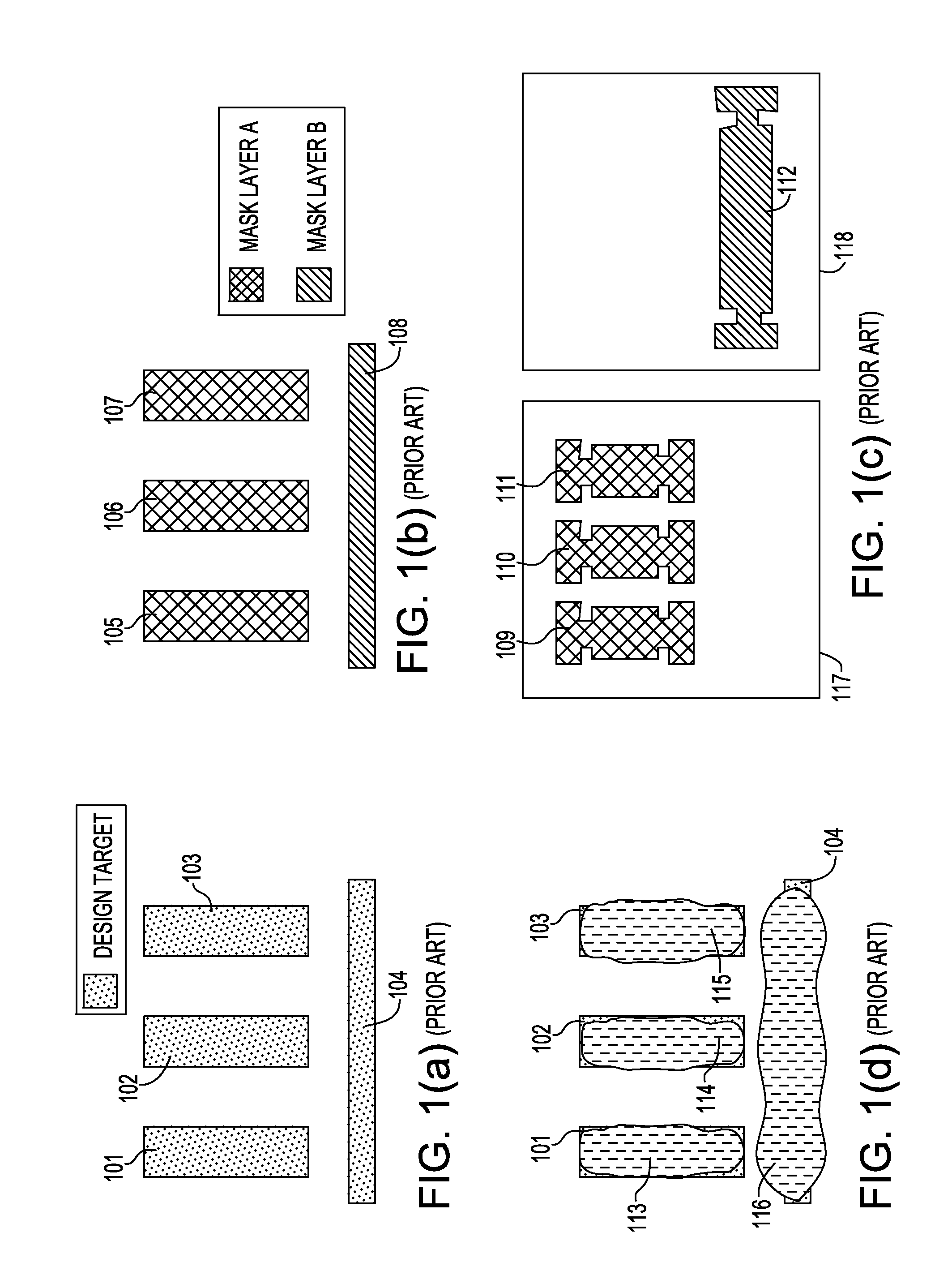
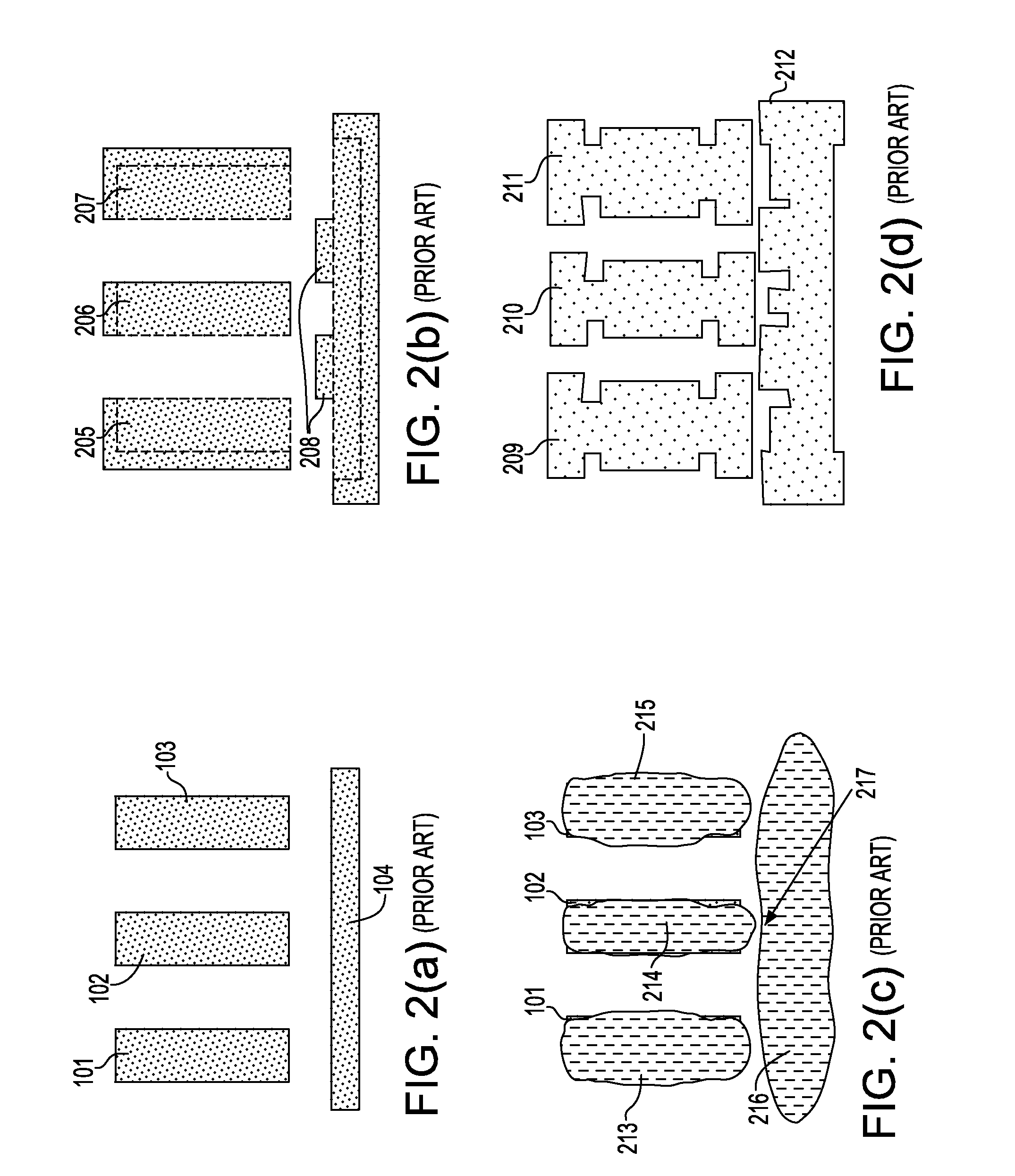
[0016]Accordingly, there is a need in the semiconductor industry for a method for generating tolerance bands on a pre-decomposed layout and for decomposing the tolerance bands, rather than target shapes, for use in subsequent data preparation for each of the individual masks. In doing so, retargeting allowances can be well balanced between each mask design while also ensuring no risk of pattern failure.
[0017]In one aspect of the invention, a method and a data structure are provided that enable decoupling the RET techniques, making it possible to achieve improved and potentially optimized results.
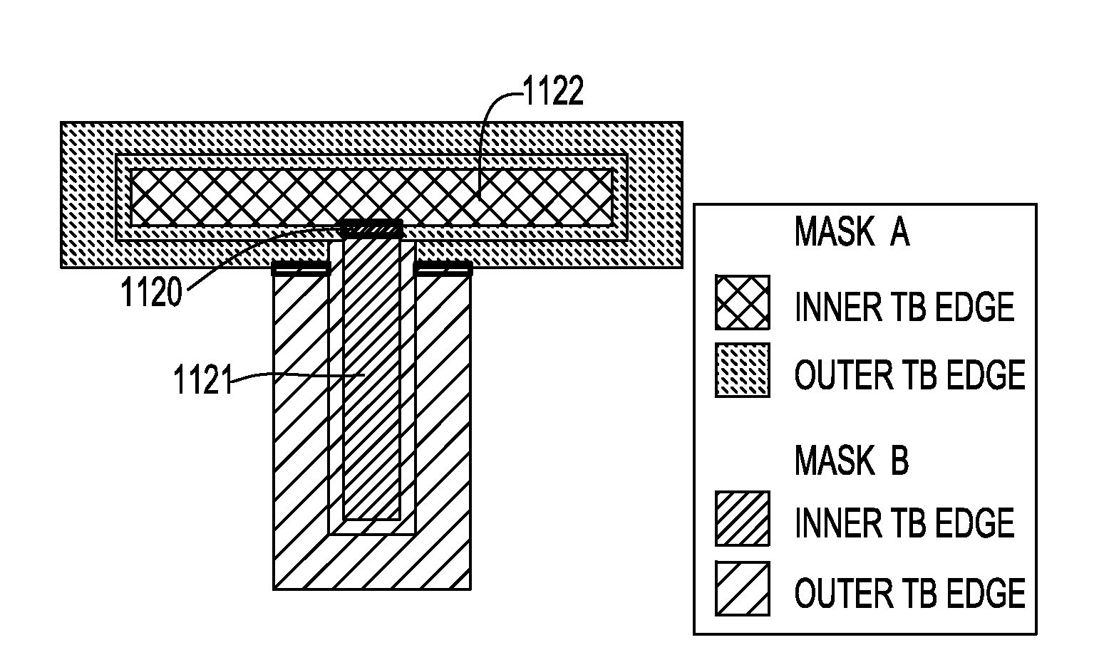
[0018]In another aspect, the invention decomposes tolerance bands onto two or more masks for use in a multi-exposure process. By using tolerance bands to convey the available target edge leeway, data preparation steps that occur after the decomposition acquire a certain desirable flexibility in setting the final printed dimensions while also protecting against the possibility of merging shap...
PUM
 Abstract
Description
Claims
Application Information