Flow measuring apparatus

a technology of flow measurement and measuring apparatus, which is applied in the direction of indirect mass flowmeter, volume/mass flow by differential pressure, liquid/fluent solid measurement, etc., can solve the problems of not fully avoiding, reducing reliability, and increasing apparatus cos

Active Publication Date: 2011-11-10
XSENS
View PDF7 Cites 101 Cited by
  • Summary
  • Abstract
  • Description
  • Claims
  • Application Information

AI Technical Summary

Benefits of technology

[0012]The present invention seeks to provide a more robust and simpler flow measuring apparatus for measuring at least flow velocity in fluids, for example in complex multiphase mixtures of fluids.
[0014]The invention is of advantage in that:(a) the flow measuring apparatus is operable to employ Lamb waves propagating in the one or more walls, which transmit ultrasonic energy to and receive ultrasonic energy from the fluid flow at any point between the at least two transducers; in consequence, the distance between a pair of transducers of the transducer arrangement is not a critical parameter for the sound propagation path; and(b) the first Lamb wave propagation path which is solely within the one or more conduit walls acts as a reference for enabling accurate and reliable measurement of fluid flow velocity and sound velocity to be achieved from ultrasonic pulse propagation time measurements.
[0019]Optionally, the apparatus is implemented such that the transducer arrangement includes a plurality of pairs of transducers for measuring spatially differential fluid flows within the conduit, for example, for increased robustness for, and / or corrections for, measuring fluid flow velocity profiles in the conduit or spatial phase distributions in the conduit if more than one fluid phase is present in the conduit.
[0020]Optionally, the apparatus is implemented such that the attenuation of the ultrasonic signal following the first path can be monitored to provide input to a frequency tuning arrangement for tuning operation of the apparatus for providing in operation optimal energy transfer between the transducer arrangement and the fluid.
[0028]Optionally, the method includes arranging for the transducers arrangement to include a plurality of pairs of transducers for measuring spatially differential fluid flows within the conduit, for example for increasing robustness of measurements for, and / or corrections for:(a) fluid flow velocity profiles in the conduit; or(b) spatial phase distributions if more than one fluid phase is present in the conduit.

Problems solved by technology

Disclosures in these US patents indicate different ways to compensate for temporal uncertainties due to variable transducer delay and propagation path, which the conventional method is sensitive to, but they do not propose any approach to fully avoid any of these problems.
Such adjustments are impractical in many applications and potentially can give rise to increased apparatus cost, extra complexity and reduced reliability.
The apparatus may enable practical installation in a clamp-on manner, but does not compensate for measurement uncertainty due to variations in temperature and fluid composition.
However, the measurement system is subject to other uncertainties, namely related to the skip distance and ultrasonic beam width.
Moreover, the measurement system may operate at frequencies which are too high for multiphase flow measurements, for example as pertinent to oil industries.
A need to add temperature and pressure measurement to conventional fluid flow measurement apparatus represents an added complexity and cost.
Such effort has resulted in complex instruments which experience measurement accuracy difficulties when presented with complex flow mixtures, for example multiphase liquid / gas mixtures including particulate matter.
However, hitherto, despite extensive effort as elucidated in the foregoing, no alternative methods have been disclosed that keep the advantages but avoid the aforementioned inherent uncertainty of ultrasonic transit-time flow measurement.

Method used


Image

  • Flow measuring apparatus
  • Flow measuring apparatus
  • Flow measuring apparatus

Examples


Embodiment Construction

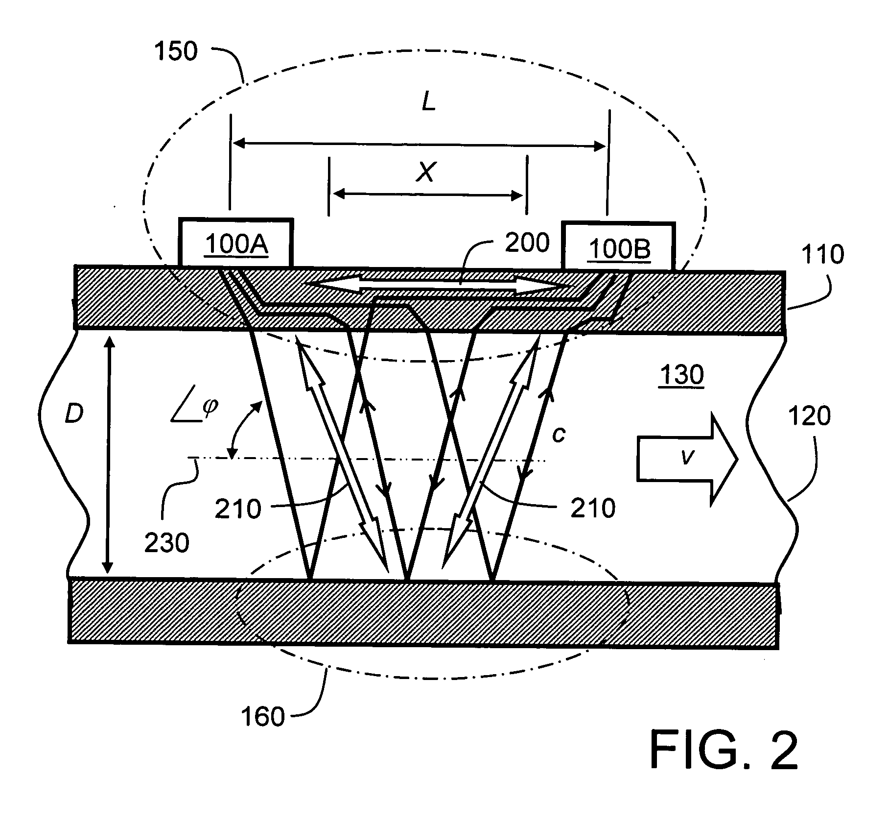
[0043]Flow measuring apparatus pursuant to the present invention employs at least two transducers 100A, 100B which are mounted onto an outer surface of a wall 110 of a conduit 120 which guides a flow of a fluid 130 when in operation. The transducers 100A, 100B are spatially mounted with a distance L between them in an axial direction of the conduit 120 as illustrated in FIG. 2. The transducers 100A, 100B are mounted onto a first portion 150 of the wall 110 as illustrated. Moreover, a second portion 160 of the wall 110 is opposite and parallel to the first portion 150 of the wall 110 as illustrated. The second portion 160 of the wall 110 is operable to reflect acoustic energy from the fluid 130 on account of the conduit 120 having a suitable, e.g. circular or rectangular profile. Beneficially, the conduit 120 is circular and has a substantially constant diameter in a region between the transducers 100A, 100B at the first and second portions 150, 160. Ultrasonic radiation transmitted ...


PUM


Abstract

A flow measuring apparatus (300, 500) measures a fluid flow (130) within a conduit (120) including a wall (110). The apparatus (300, 500) includes a transducer arrangement including at least two transducers (100A, 100B) for alternately emitting and receiving ultrasonic radiation through the conduit wall (110) and the flow (130). The apparatus (300, 500) also includes a signal processing arrangement (310) for generating signals to excite the transducer arrangement (100A, 100B) and for processing received signals provided by the transducer arrangement (100A, 100B) for generating output signals from the signal processing arrangement (310) indicative of properties of the flow. The transducer arrangement (100A, 100B) in cooperation with the conduit (120) provides a first path (200) for Lamb-wave ultrasonic radiation coupling directly from a first of the at least two transducers (100A, 100B), to a second of said at least two transducers to generate a first received signal. The transducer arrangement (100A, 100B) in cooperation with the conduit (120) provides at least one second path (210) for ultrasonic propagation along the wall (100) via Lamb waves coupling to at least a portion of the flow (130) from a first of the at least two transducers (100A, 100B) to a second of the at least two transducers (100A, 100B) to generate a second received signal. The signal processing arrangement (310) determines from said first and second received signals ultrasonic radiation propagation time periods through the first path (200) and through the at least one second path (210), and to perform computational operations on the propagation time periods to determine properties of the flow including, but not limited to, at least one of: fluid flow velocity (v) in the conduit (120), a sound velocity (c) through the fluid (130).

Description

TECHNICAL FIELD OF INVENTION[0001]The present invention relates to flow measuring apparatus, for example to a flow measuring apparatus for measuring a flow velocity and a sound velocity of a fluid flowing through a conduit by utilizing at least two ultrasonic transducers mounted onto an outer surface of the conduit. Moreover, the invention relates to a method of measuring flow velocity and sound velocity of a fluid, for example to a method of measuring flow velocity and sound velocity in a fluid by utilizing at least two ultrasonic transducers mounted onto an outer surface of a conduit.BACKGROUND TO THE INVENTION[0002]Ultrasonic transit-time flow measurement is well known for measuring fluid flow velocities through conduits. Moreover, such flow measurement is feasible without introducing mechanical obstructions to the flow. In addition to an advantage of such non-obstructiveness, ultrasonic flow measuring apparatus often offer a relatively low cost of installation and operation. Thi...

Claims


Application Information

Patent Timeline
Patent Type & Authority Applications(United States)
IPC IPC(8): G01F1/66
CPCG01F1/42G01F1/662G01N2011/0073G01F1/86G01N9/24G01F1/667
Inventor KIPPERSUND, REMI ANDREFROYSA, KJELL EIVINDLUNDE, PER
Owner XSENS
Why Eureka
Try Eureka