Sand production control through the use of magnetic forces

a technology of magnetic force and production control, applied in the direction of wellbore/well accessories, fluid removal, survey, etc., can solve the problems of limiting the ability of sand particles to traverse through the pores within the underground formation, and limit the amount of sand produced, so as to reduce the amount of produced sand

Active Publication Date: 2011-11-10
SAUDI ARABIAN OIL CO
View PDF6 Cites 4 Cited by
  • Summary
  • Abstract
  • Description
  • Claims
  • Application Information

AI Technical Summary

Benefits of technology

[0004]The present invention is directed to a process that satisfies at least one of these needs. The invention includes a process for reducing the amount of produced sand from an underground formation through the use of magnetic forces. The process includes providing magnetized loose sand particles. In one embodiment, providing the magnetized loose sand particles includes the steps of magnetizing a portion of loose sand particles that is located within the underground formation in a producing section adjacent to a wellbore. An alternate embodiment of providing magnetized loose sand particles includes identifying loose sand particles that are compositionally magnetic. After providing the magnetized loose sand particles, a magnetic force is applied from a magnet source to the magnetized loose sand particles in the producing section of the underground formation, and hydrocarbons are produced from the underground formation via the wellbore. In one embodiment, the ma

Problems solved by technology

Preferably, this causes the sand particles to stick together, even in the absence of an applied magnetic field, which advantageously limits the sand particles' ability to trav

Method used


Image

  • Sand production control through the use of magnetic forces
  • Sand production control through the use of magnetic forces
  • Sand production control through the use of magnetic forces

Examples


Embodiment Construction

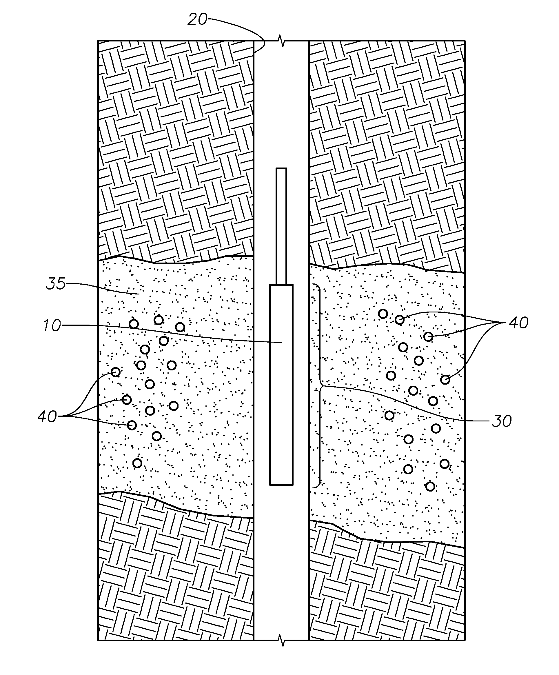
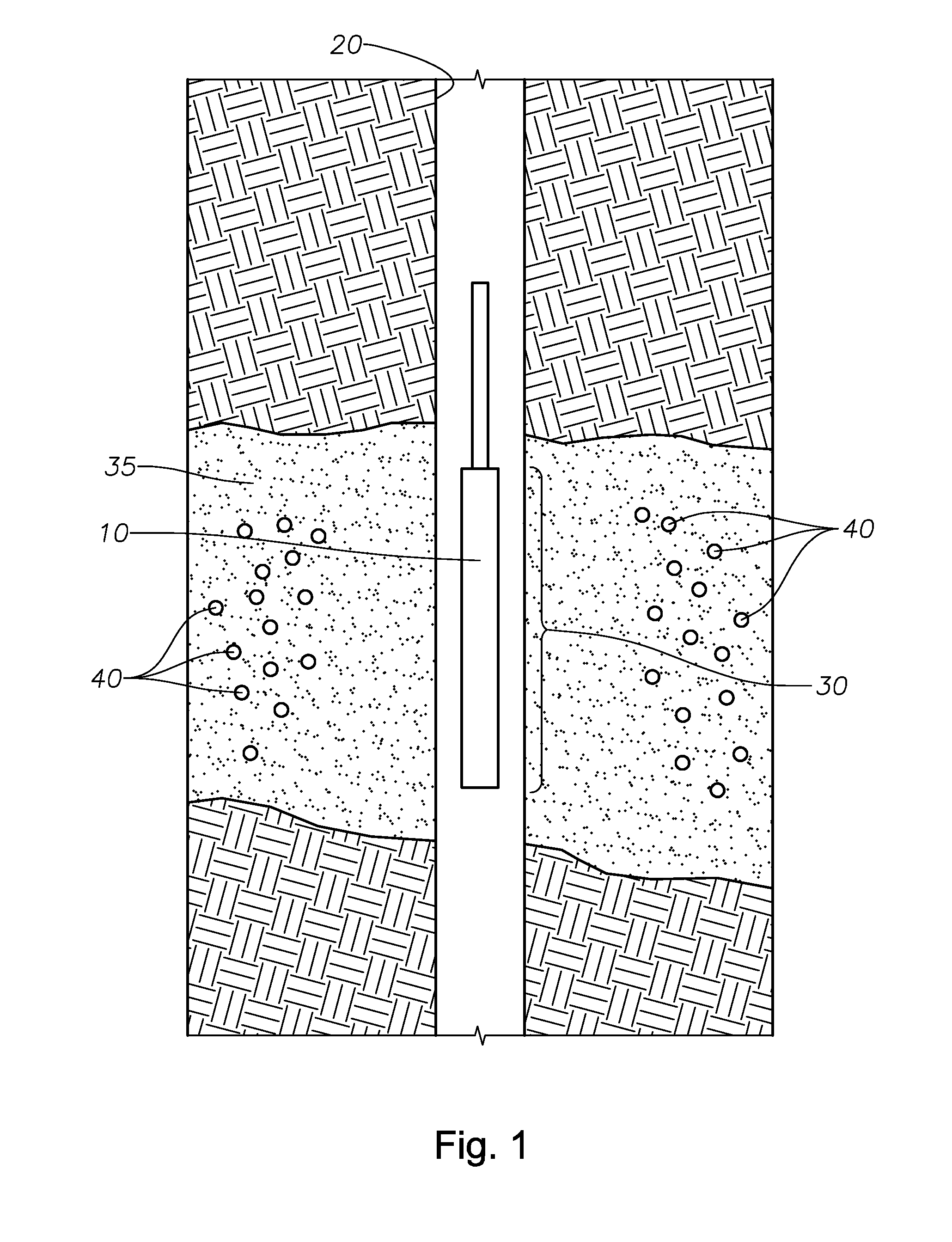
[0020]In FIG. 1, magnet source 10 is disposed within wellbore 20 proximate producing section 30 of the underground formation. Magnetized loose sand particles 40 can be either repelled or attracted to magnet source 10 depending upon the desired function. For example, in one embodiment of the present invention, the polarity of magnet source 10 and magnetized loose sand particles 40 are the same, such that magnetized loose sand particles 40 experience a repulsive force. In another embodiment of the present invention, the polarities of magnet source 10 and magnetized loose sand particles 40 can be opposite, such that magnetized loose sand particles 40 experience a pulling force towards magnet source 10. This can advantageously allow for a controlled cleaning of the underground formation of magnetized loose sand particles 40. In one embodiment, the magnet source is proximal to the formation perforations. Magnet Sales & Manufacturing Company, Inc provides customizable magnets. Those of or...


PUM


Abstract

A process for controlling the production of loose sand particles within an underground formation through the use of magnetic forces is provided. The loose sand particles are magnetized and then subjected to a magnetic field of sufficient strength such that the operator can control the movement of the loose sand particles within the underground formation. In some instances, the present invention can provide an efficient process for keeping the loose sand particles within the formation, and thereby prolonging the useful life of the downhole equipment. In other instances, the present invention can provide an efficient process for sweeping the loose sand particles out of the underground formation in a controlled fashion. The present invention includes at least three embodiments for magnetizing the loose sand particles, including direct magnetization, contacting the sand particles with a magnetizing reagent, and contacting the sand particles with paramagnet nanoparticles.

Description

FIELD OF THE INVENTION[0001]The present invention relates to a method for controlling the amount of sand produced from a wellbore. More particularly, the present invention relates to a method of using magnetic forces to control the flow of loose sand particles within an underground formation to prevent the loose sand particles from damaging downhole tools.DESCRIPTION OF THE RELATED ART[0002]A typical wellbore includes a production zone from which well fluid is produced and communicated to the surface of the well through a production string. At certain locations along the production string, small perforations are formed in order to allow well fluid to enter the production string from an underground formation. However, during drilling of the wellbore, particularly in unconsolidated or poorly consolidated formations, the radial area surrounding the wellbore is exposed to high tangential stresses, with the extra stress resulting in an increase in loosely held sand particles within the u...

Claims


Application Information

Patent Timeline
IPC IPC(8): E21B43/00E21B47/00E21B43/02E21B41/00E21B37/00
CPCE21B43/04E21B43/025
Inventor AL-TAHINI, ASHRAF
Owner SAUDI ARABIAN OIL CO
Why Eureka
Try Eureka