Electrochemical Biosensor Structure and Measuring Method Using the Same

a biosensor and electrochemical technology, applied in the field of electrochemical biosensor structure and measurement method using the same, can solve the problems of affecting the measurement, affecting the accuracy of measurement, and distortion of the measurement signal of the biosensor, so as to reduce the effect of double layer capacitance, accurately detect the time and velocity of the sample insert, and achieve the effect of faster sample measuremen

Active Publication Date: 2011-11-10
ANDONG NAT UNIV IND ACADEMIC COOPERATION FOUND +1
View PDF6 Cites 12 Cited by
  • Summary
  • Abstract
  • Description
  • Claims
  • Application Information

AI Technical Summary

Benefits of technology

[0033]The present invention minimizes the effect of the double layer capacitance, independently applies the sample recognition signal, and accurately detects the sample insert time and velocity irrespective of the viscosity of the sample to be measured. Additionally, the present invention has no problem in regard to a distortion of the measurement signal in taking a measurement of the sample, so the sample measurement can be accomplished more rapidly with high reproducibility.

Problems solved by technology

This case encounters a problem that the sample insertion detection signal applied to detect the sample insert timing is too early reactive to the sample on the surface of the working electrode and the reference electrode, which are important as electrodes for measurement, to form an electric double layer (EDL).
This causes a distortion of the measurement signal of the biosensor and affects the measurement results.
It is therefore considerably problematic in regard to accuracy of measurement to determine the timing to apply the sample measurement signal by control of timing.

Method used


Image

  • Electrochemical Biosensor Structure and Measuring Method Using the Same
  • Electrochemical Biosensor Structure and Measuring Method Using the Same
  • Electrochemical Biosensor Structure and Measuring Method Using the Same

Examples


Embodiment Construction

[0039]Hereinafter, the preferred embodiments of the present invention will be described in detail with reference to the accompanying drawings, which are intended for purpose of illustration only and are not intended to limit the scope of the invention.

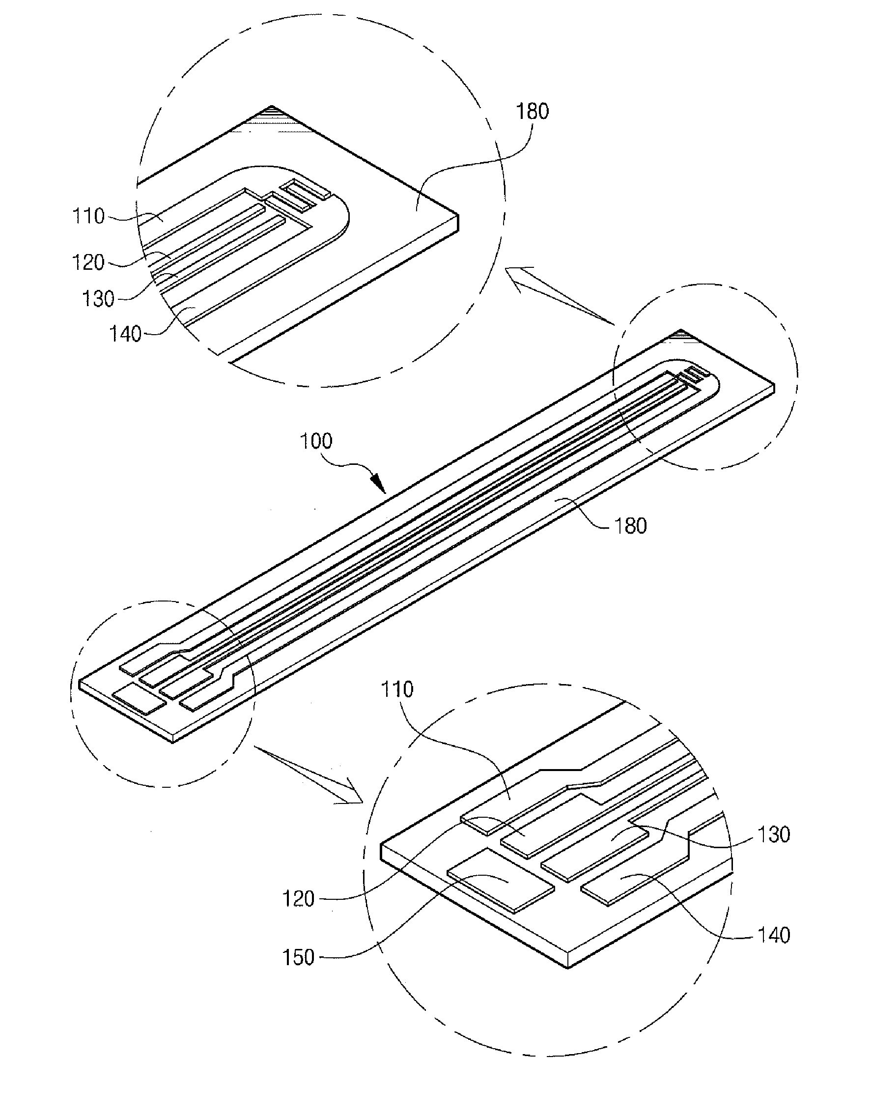
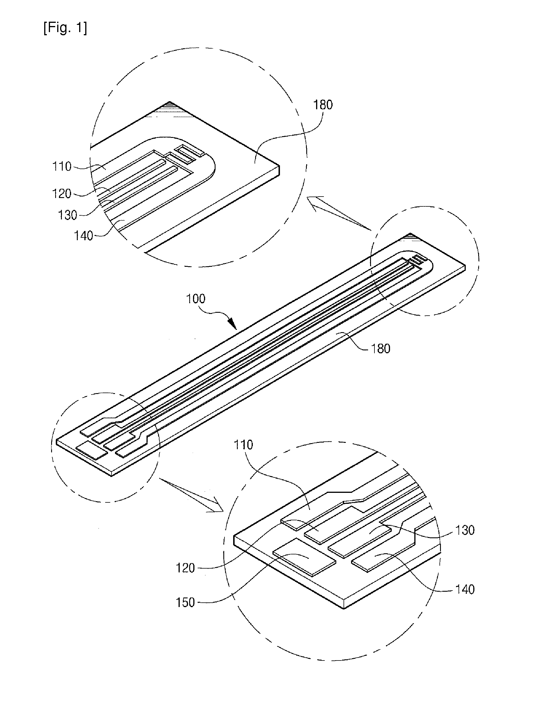
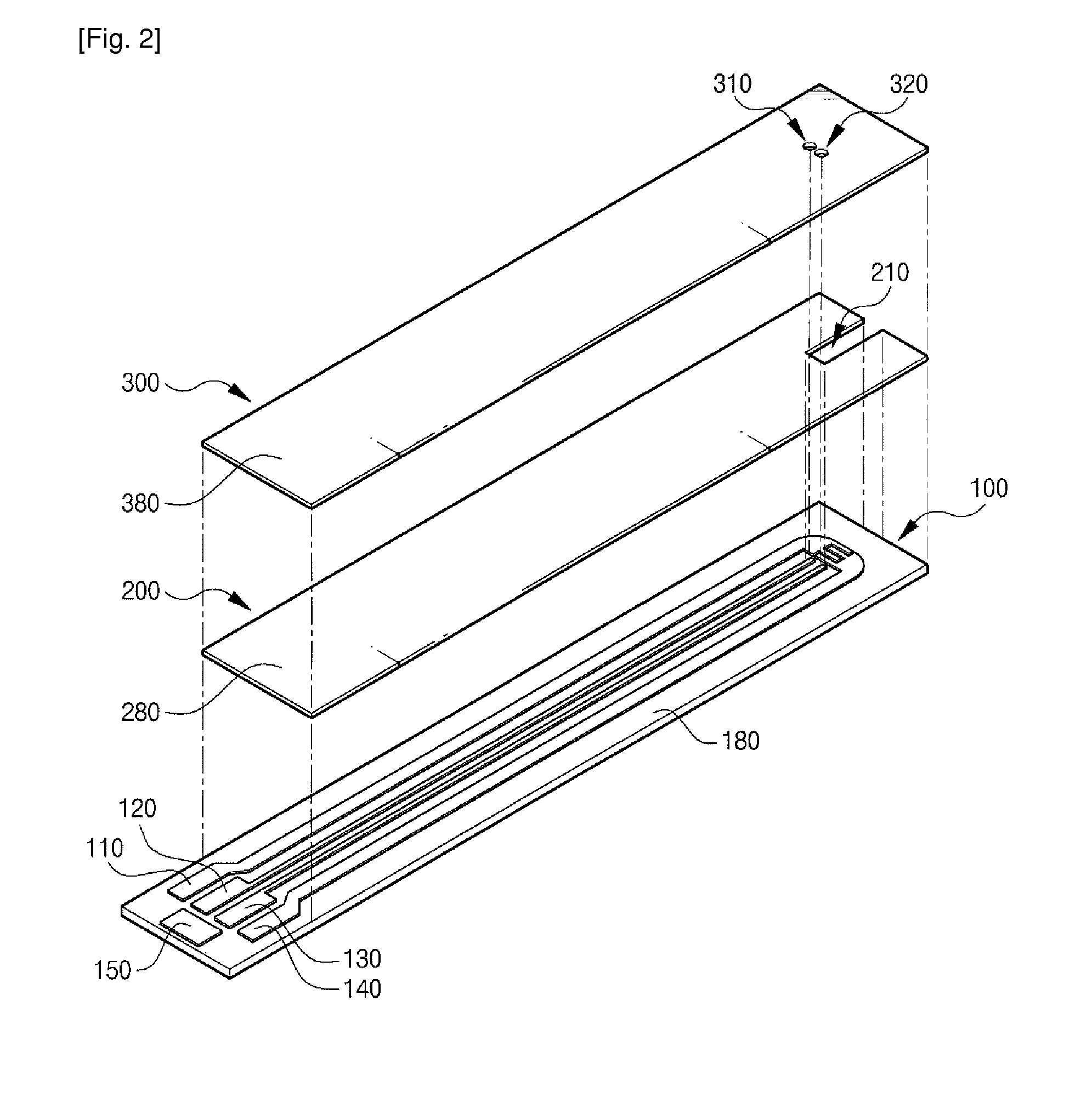
[0040]FIG. 1 shows an electrochemical biosensor electrode structure according to an embodiment of the present invention.

[0041]As illustrated in FIG. 1, biosensor electrodes 110, 120, 130 and 140 according to an embodiment of the present invention are fabricated on an insulating substrate 100. The method for fabricating the biosensor electrodes 110, 120, 130 and 140 is illustrated in FIGS. 8 to 14.

[0042]The biosensor electrodes 110, 120, 130 and 140 include a working electrode 110 and a reference electrode 140 used as electrodes for sample measurement, and at least two sample recognition electrodes 120 and 130 used as electrodes for sample recognition.

[0043]Generally, two electrodes are used in measuring the electric potential differenc...


PUM

PropertyMeasurementUnit
separation distanceaaaaaaaaaa
distanceaaaaaaaaaa

Abstract

The present invention provides there is provided an electrochemical biosensor electrode structure that includes: a working electrode and a reference electrode used as electrodes for sample measurement being arranged separately from each other in lengthwise direction of a sample insertion path, the working electrode and the reference electrode each having at least one projection and at least one recess alternately arranged on a portion thereof corresponding to the sample insertion path, the projection of the working electrode being correspondingly adjacent to the recess of the reference electrode, the recess of the working electrode being correspondingly adjacent to the projection of the reference electrode; and at least two sample recognition electrodes used as electrodes for sample recognition being separated from each other and arranged adjacent and parallel to the working electrode and the reference electrode. The present invention minimizes the effect of the double layer capacitance and independently applies the sample recognition signal to accurately detect the sample insert time and velocity.

Description

TECHNICAL FIELD[0001]The present invention relates to an electrochemical biosensor structure and a measurement method using the same, and more particularly, to an electrochemical biosensor electrode structure and a measurement method using the same that minimizes double layer capacitance and thereby can realize rapid and accurate measurements of response signals to a bio sample.BACKGROUND ART[0002]It is chemically and clinically important to do qualitative and quantitative analyses of materials contained in a bio sample, including, for example, blood glucose for diabetic patients or cholesterol in blood that is a factor of many adult diseases.[0003]As known in the art, measuring enzymatic activity for a specific material contained in a bio sample (hereinafter, referred to as “sample”) more rapidly with good reproducibility is very important to the electrochemical biosensor using enzymatic activity such as, for example, glucose sensor, uric acid sensor, protein sensor, DNA sensor or ...

Claims


Application Information

Patent Timeline
Patent Type & Authority Applications(United States)
IPC IPC(8): G01N27/327G03F7/20G01N33/50
CPCG01N27/3272G01N27/26G01N27/30
Inventor LEE, YOUNG TAEKIM, KYU JUNSUH, HO CHULKIM, TAE WAN
Owner ANDONG NAT UNIV IND ACADEMIC COOPERATION FOUND
Why Eureka
Try Eureka