Electrical driven flying saucer based on magnetic suspension

a technology of magnetic suspension and saucer shell, which is applied in the field of electric driven flying saucers based on magnetic suspension, can solve the problems of limited interior space of saucer shell, serious accidents, and restrict the structure and layout of rotary-wing systems and their power systems, and achieves compact structure, reasonable layout, and small weight

Inactive Publication Date: 2011-11-10
BEIJING UNIV OF TECH
View PDF4 Cites 25 Cited by
  • Summary
  • Abstract
  • Description
  • Claims
  • Application Information

AI Technical Summary

Benefits of technology

[0005]The object of the present invention is to make full use of the limited internal space of the saucer shell and design and construct a rotary-wing flying saucer which has a compact structure, reasonable layout, small weight, high motive power conversion efficiency and owns an easily manipulated and controlled rotary-wing system and its power system.
[0010]As an improvement of the present invention, two sets of independent magnetic suspension electromotive rotary-wing systems are superposed and mounted coaxially inside the saucer shell in the axial direction (Y-Y), i.e. the upper rotary-wing system and the lower rotary-wing system. Coaxial axial dual magnetic suspension electromotive rotary wings are formed, wherein the upper rotary-wing system and the lower rotary-wing system rotate in reverse directions, adopt reverse inclination directions of blades, can guarantee the coaxial thrusts in the same direction will overcome or offset the reactive torque generated during rotation of the rotary wings and may realize automatic control for self-rotating angles and self-rotating angular velocity of the flying saucer through controlling the velocities and velocity difference of the upper rotary-wing system and the lower rotary-wing system.
[0011]As an alternative improvement of the present invention, two sets of independent magnetic suspension electromotive rotary-wing systems are superposed and mounted coaxially inside the saucer shell in a radial direction (X-X), i.e. the inner rotary-wing system and the outer rotary-wing system. Coaxial radial dual magnetic suspension electromotive rotary wings are formed, wherein the inner rotary-wing system and the outer rotary-wing system rotate in reverse directions, adopt reverse inclination directions of blades, can guarantee the coaxial thrusts in the same direction will overcome or offset the reactive torque generated during rotation of the rotary wings and may realize automatic control for self-rotating angles and self-rotating angular velocity of the flying saucer through controlling the velocities and velocity difference of the inner rotary-wing system and outer rotary-wing system.
[0012]The magnetic suspension electromotive flying saucer designed in the present invention makes full use of the limited internal space of the saucer shell and has a compact design structure, reasonable layout, small weight and high motive power conversion efficiency. Further, its rotary-wing system and power system can be easily manipulated and controlled. The design of the rotary-wing suspension structure avoids the contact and friction between the high-speed rotary-wing and the interior of the saucer shell, reduce the noise of the rotary wing during high-speed rotation as well as the vibration of the saucer shell and the saucer cabin, raise motive power conversion efficiency, lower energy consumption and guarantee the operational safety of the rotary wing and the flying saucer. The two improvement solutions mentioned in the present invention overcome the problem of reactive torque of the rotary wing under the precondition of meeting the foregoing requirements, and can realize stable and easy power control of the rotary wing.

Problems solved by technology

The internal space of the saucer shell is limited and restricts the structure and layout of the rotary-wing system and its power system.
When the rotary wing rotates at a high speed in the saucer shell, due to pneumatic vortex, flexibility of the rotary wing, maneuver of the saucer and other factors, the rotary wing and the saucer shell might collide with each other, resulting in failure and even a serious accident.
There is the problem that the body of the flying saucer suffers uncontrollable reactive torque.

Method used


Image

  • Electrical driven flying saucer based on magnetic suspension
  • Electrical driven flying saucer based on magnetic suspension
  • Electrical driven flying saucer based on magnetic suspension

Examples


embodiment 1

Single-Rotary-Wing Electrical Driven Flying Saucer Based on Magnetic Suspension

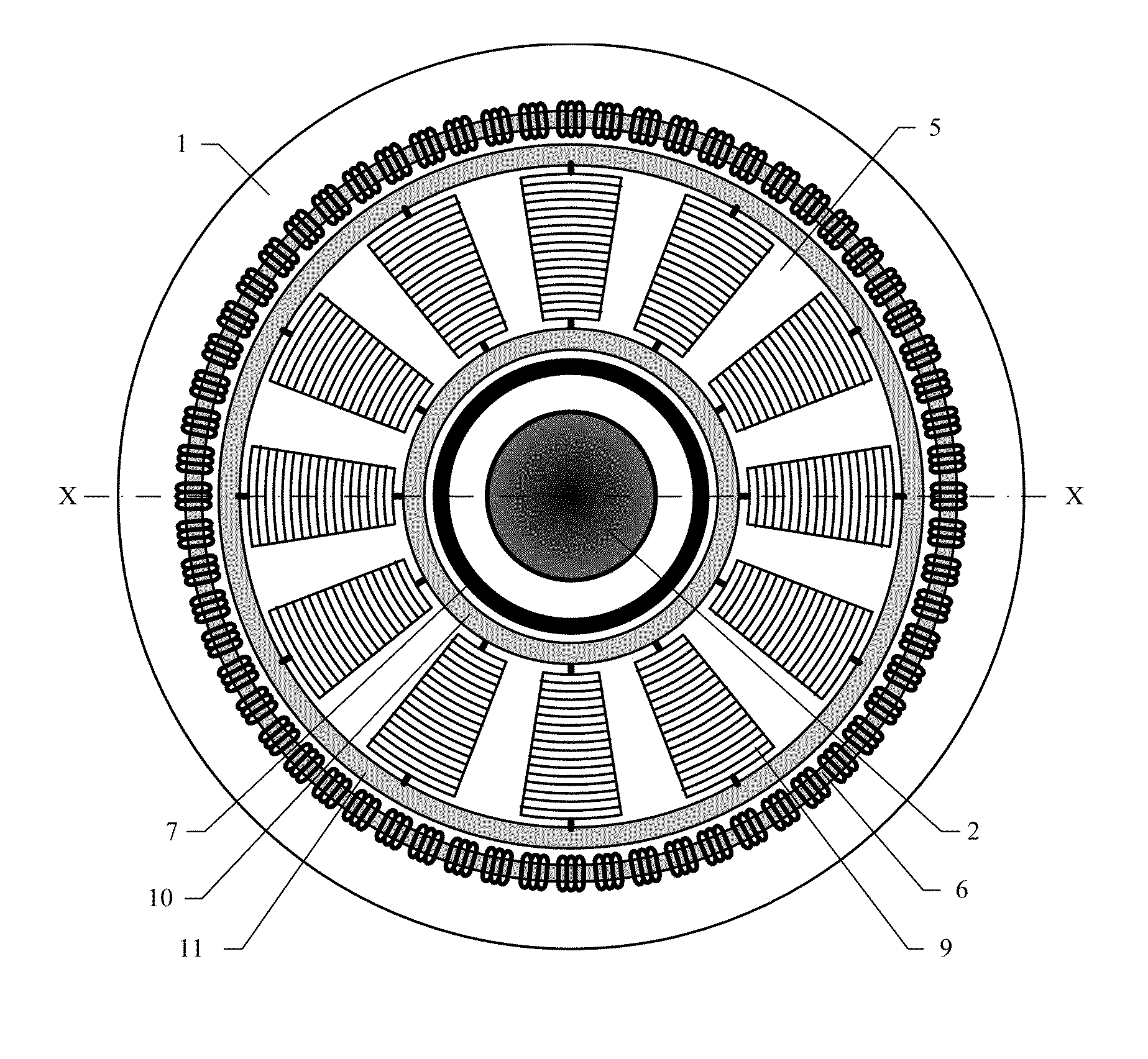
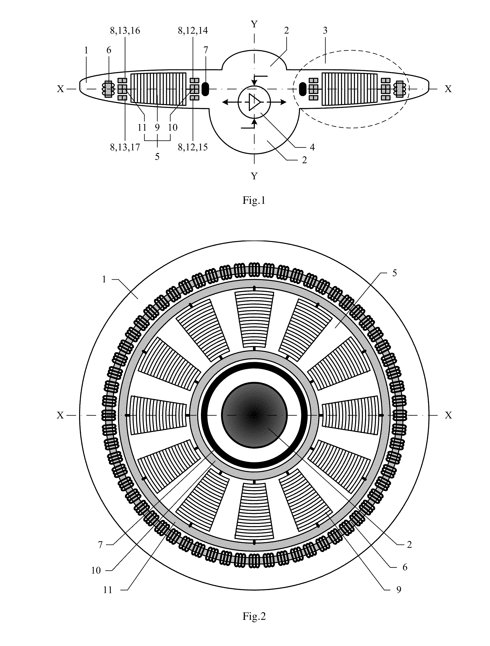
[0021]In reference to FIG. 1 and FIG. 2, the single-rotary-wing electrical driven flying saucer based on magnetic suspension comprises: a saucer shell 1, a saucer cabin 2, a rotary-wing system 3 and a control system 4, wherein the rotary-wing system 3 is a magnetic suspension electromotive rotary-wing system and comprises magnetic suspension rotary-wing wheels 5, an electromotive ring 6, a magnetic suspension shaft 7 and a magnetic suspension guide rail 8; the electromotive ring 6, the magnetic suspension shaft 7 and the magnetic suspension guide rail 8 are fixed to the saucer shell 1; the magnetic suspension rotary-wing wheels 5 comprise blades 9, an magnetic suspension inner ring 10 and a magnetic suspension outer ring 11, the blades 9 are connected to the magnetic suspension inner ring 10 and the magnetic suspension outer ring 11 along the radial direction (X-X) and form an impeller; the magnetic suspe...

embodiment 2

Radial Magnetic Suspension Structure of Rotary-Wing Wheels

[0025]An electrical driven flying saucer based on magnetic suspension is provided. Its magnetic suspension rotary-wing wheels 5 are suspended on the magnetic suspension shaft 7 in the radial direction (X-X) according to the magnetic suspension principle.

[0026]As shown in FIG. 5, a radial magnetic suspension structure of the magnetic suspension rotary-wing wheels 5 is designed, pairs of magnets 22 are placed on the outer edges of the magnetic suspension inner ring 10 and the magnetic suspension shaft 7 of the magnetic suspension rotary-wing wheels 5, the N poles of the magnets of the magnetic suspension inner ring 10 face the inside and the S poles face the outside; the S poles of the magnets of the magnetic suspension shaft 7 face the inside and the N poles face the outside. According to the principle that like poles of magnets expel, the N pole of the outer edge of the magnetic suspension inner ring 10 and the N pole of the ...

embodiment 3

Axial Magnetic Suspension Structure of Rotary-Wing Wheels

[0030]An electrical driven flying saucer based on magnetic suspension is provided. Its magnetic suspension rotary-wing wheels 5 are suspended on the magnetic suspension guide rail 8 in the axial direction (Y-Y) according to the magnetic suspension principle, i.e.: the magnetic suspension inner ring 10 is suspended between the inner ring upper guideway 14 and the inner ring lower guideway 15, and the magnetic suspension outer ring 11 is suspended between the outer ring upper guideway 16 and the outer ring lower guideway 17.

[0031]As shown in FIG. 6, an axial magnetic suspension structure of the magnetic suspension rotary-wing wheels 5 is designed to make the N poles of the magnets of the magnetic suspension inner ring 10 and the magnetic suspension outer ring 11 face upward and the S poles face downward; the S poles of the magnets of the inner ring upper guideway 14 and the outer ring upper guideway 16 face upward and the N pole...


PUM


Abstract

A magnetic suspension electric rotor flying saucer comprises: a saucer shell (1), a saucer cabin (2), a rotor system (3), and a control system (4). The rotor wing system is a magnetic suspension electric rotor wing system (3) composed of a magnetic suspension rotor wing wheel (5), an electrodynamic ring (6), a magnetic suspension shaft (7) and magnetic suspension lead rails (8). The electrodynamic ring (6), the magnetic suspension shaft (7) and the magnetic suspension lead rails (8) are fixed on the saucer shell (1). The magnetic suspension rotor wing wheel (5) is suspended in space limited by the electrodynamic ring (6), the magnetic suspension shaft (7) and the magnetic suspension lead rails (8) and rotates around the magnetic suspension shaft (7) by the electromagnetic thrust.

Description

FIELD OF THE INVENTION[0001]The present invention pertains to the field of aviation aircrafts and particularly relates to an electrical driven flying saucer based on magnetic suspension.BACKGROUND OF THE INVENTION[0002]The lift and thrust of a rotary-wing aircraft are formed by a rotary wing rotating at a high speed. The power for the rotation of the rotary wing comes from an engine. The current rotary-wing aircrafts include all kinds of rotary-wing helicopters. The rotary wing and engine are two separate and independent systems and connected with a transmission mechanism.[0003]Compared with ordinary rotary-wing aircrafts, the particularity of a rotary-wing flying saucer is that the rotary-wing system and its power system need to be installed inside a saucer shell. The internal space of the saucer shell is limited and restricts the structure and layout of the rotary-wing system and its power system. Therefore, the paramount task for the design of a rotary-wing flying saucer is how t...

Claims


Application Information

Patent Timeline
Patent Type & Authority Applications(United States)
IPC IPC(8): B64C27/00
CPCB64C27/20B64C2201/027B64C2201/042Y02T50/62B64C2201/127B64D27/24B64C2201/108Y02T50/60Y02T50/40B64U10/13B64U30/20B64U50/19B64U2101/30
Inventor RUAN, XIAO-GANGHOU, XU-YANG
Owner BEIJING UNIV OF TECH
Why Eureka
Try Eureka