Photovoltaic power plant

a photovoltaic power plant and photovoltaic technology, applied in the direction of dc-ac conversion without reversal, transportation and packaging, dc network circuit arrangement, etc., can solve the problem of detection of isolation faults in the power plant, and achieve the effect of loss of efficiency

Active Publication Date: 2011-11-10
SMA SOLAR TECH AG
View PDF5 Cites 91 Cited by
  • Summary
  • Abstract
  • Description
  • Claims
  • Application Information

AI Technical Summary

Benefits of technology

[0017]Therefore, it is an object of the invention to provide a PV power plant comprising PV strings in which the grounding regime of the PV strings hinders degradation and loss of efficiency.

Problems solved by technology

Furthermore, isolation faults in the power plant may be detected by monitoring the current flowing from the offset voltage source.

Method used


Image

  • Photovoltaic power plant
  • Photovoltaic power plant
  • Photovoltaic power plant

Examples


first embodiment

[0061]The advantages of this embodiment are similar to the advantages already given for the first embodiment discussed above. In addition, it will be seen that there is no requirement to ground the appropriate input of each inverter 4, 38 individually since the offset voltage source 14 controls the voltage relative to ground on the isolated AC side of all the inverters 4, 38 to a reference point. This reference point could be set to any desired potential between positive or negative side of the PV string and thus compensate for different problems associated with different PV cell type discussed above.

[0062]The reference point could also be made programmable, that is it can be varied according to the type of PV string being used, or by some other criteria. It also could be set as a function of time and thus it would be possible to changed the settings of the offset voltage during the day if required.

[0063]Since the offset voltage is being produced at a single point in the circuit, an...

third embodiment

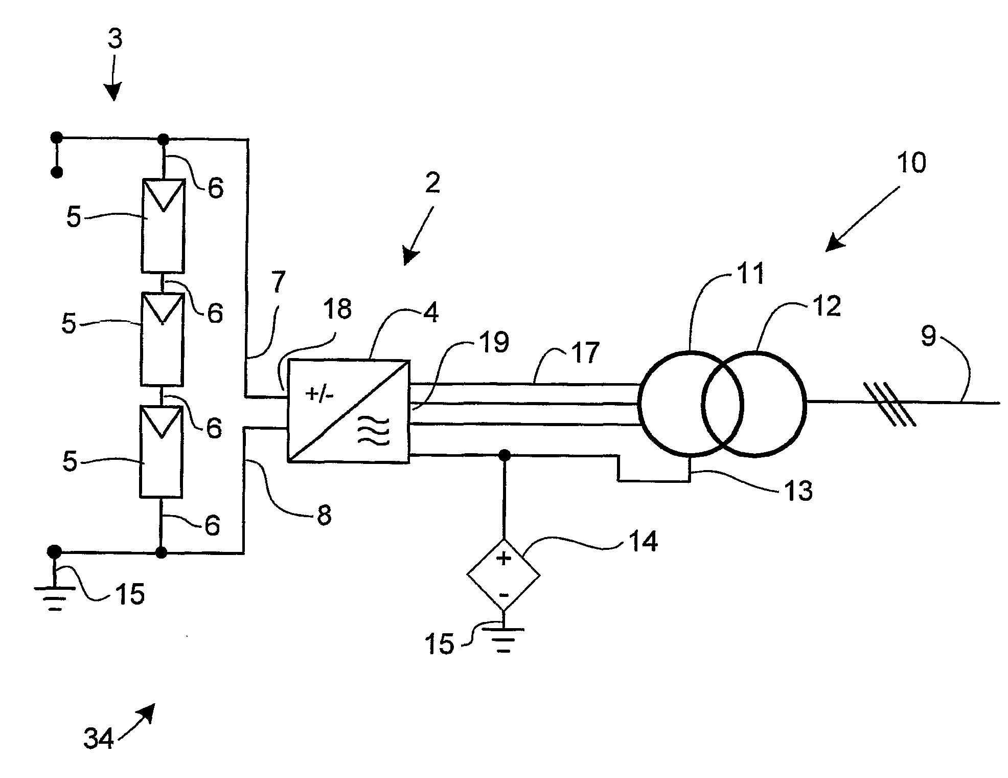
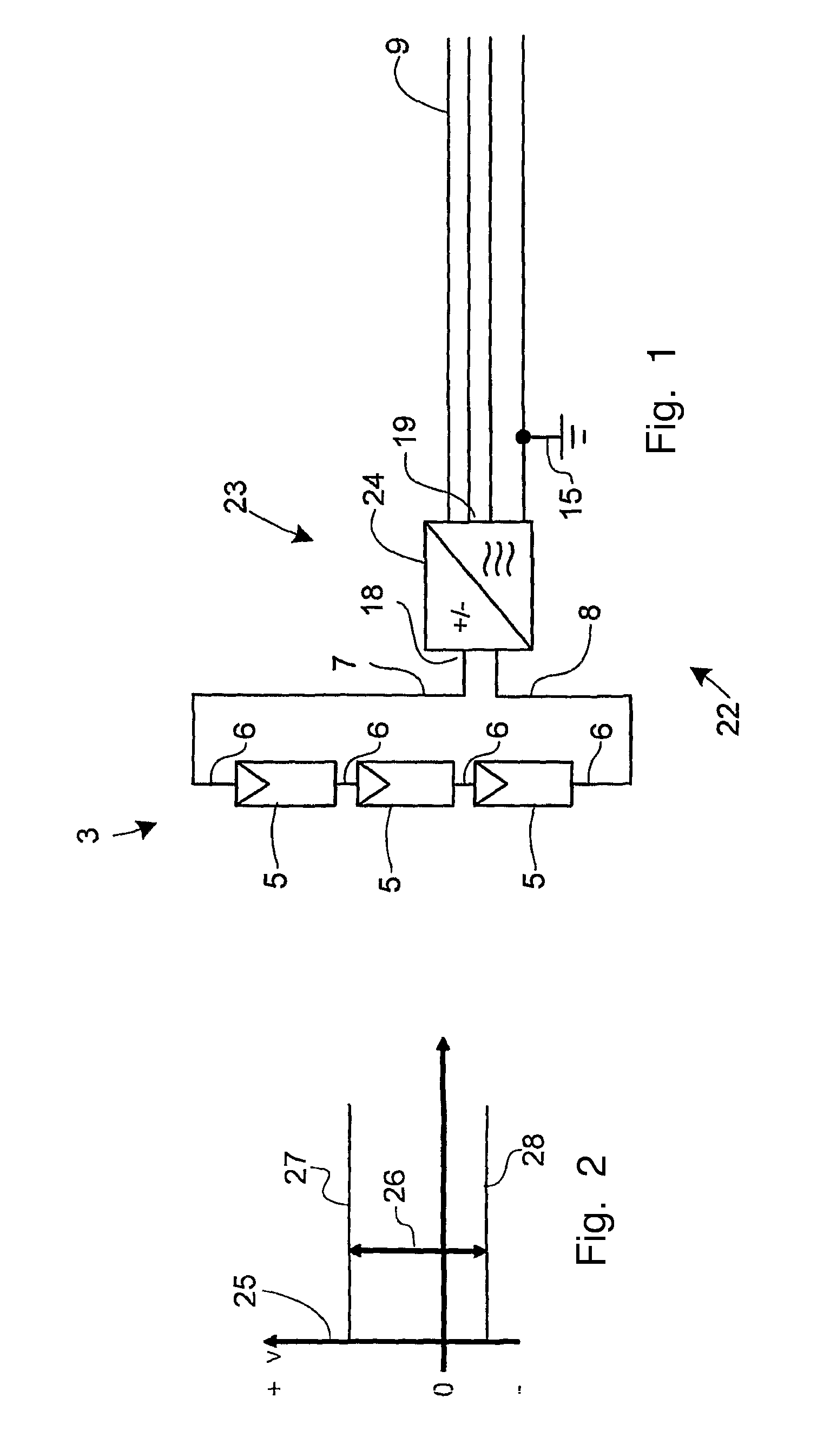
[0065]FIG. 10 shows the invention. This is similar to the embodiment illustrated in FIG. 7, but with the addition of a second PV generator 2, and with each PV string 3 comprising four PV modules 5 connected in series. The offset voltage source 14 comprises two offset PV modules 16 connected in series. The offset PV modules 16 are similar in construction to the PV modules 5 of the PV generators 2.

[0066]The number of offset PV modules 16 equals half the number of PV modules 5 in a PV string 3, wherefore the output voltage of the offset voltage source 14—the offset voltage—equals approximately half of the PV string DC voltages. Most of the time, the offset voltage source 14 is less loaded than the PV strings, wherefore most of the time, the offset voltage will be a little higher than half of the PV string DC voltages.

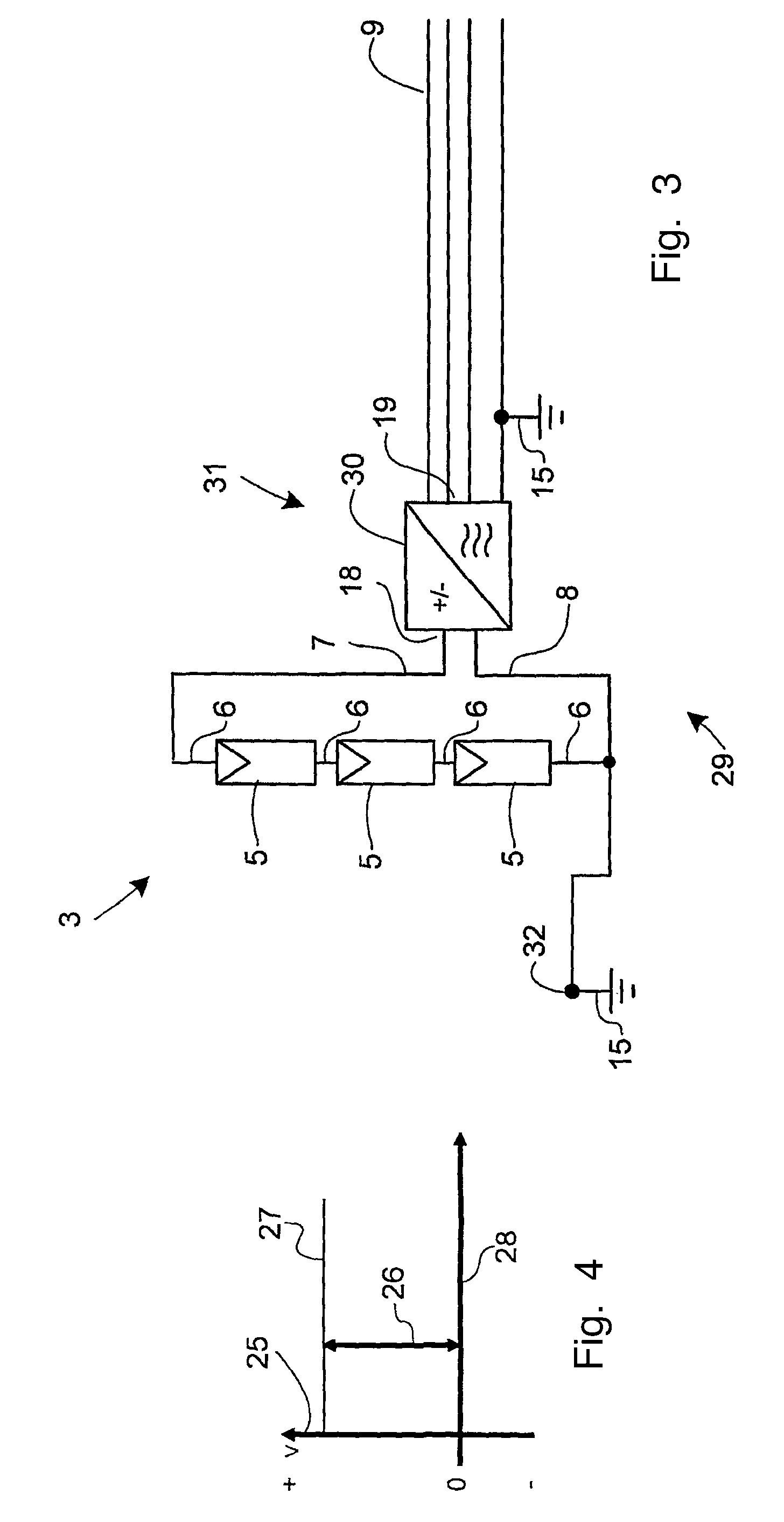
[0067]Instead of using an equalising circuit, the DC potential at the DC input 18 of the inverters 4 may be controlled actively by the inverter control circuits. This is f...


PUM


Abstract

In large PV power plants, grounding of individual PV modules may lead to problems. The present invention overcomes such problems. The basis for the invention is a PV power plant comprising one or more PV generators, each comprising a PV string and an inverter with a DC input and an AC output. The PV string comprises at least one PV module and is electrically connected to the DC input of the inverter. The inverter comprises means for controlling the DC potential at the DC input depending on the DC potential at the AC output. The AC outputs of the inverters are coupled in parallel. The novel feature of the invention is that the PV power plant further comprises an offset voltage source, which controls the DC potential at the AC outputs. Thereby, the DC potential at the DC input will be indirectly controlled, and it is thus possible to ensure that the potentials with respect to ground at the terminals of the PV modules are all non-negative or all non-positive without grounding the PV modules. Ground loops can be avoided, and there is no need for the use of transformer-based inverters.

Description

CROSS REFERENCE TO RELATED APPLICATIONS[0001]This application is entitled to the benefit of and incorporates by reference essential subject matter disclosed in International Patent Application No. PCT / DK2009 / 000231 filed on Nov. 6, 2009 and Danish Patent Application No. PA 2008 01537 filed Nov. 7, 2008; and Danish Patent Application No. 2009 00896 filed on Jul. 24, 2009.FIELD OF THE INVENTION[0002]The invention regards a photovoltaic (PV) power plant.BACKGROUND OF THE INVENTION[0003]In larger PV power plants with DC / AC-converters (inverters), the plant is typically connected to the power grid through a dedicated isolation transformer, which connects the relatively low voltage PV generator system to the medium voltage power grid. One reason for this is that the PV modules, which convert the solar energy into electrical energy, typically must have a defined potential with respect to ground. This is typically achieved by grounding all or some of the PV modules.[0004]Grounding is normal...

Claims


Application Information

Patent Timeline
Patent Type & Authority Applications(United States)
IPC IPC(8): H02J3/04
CPCH02J3/383Y02E10/563H02M7/48H02J2300/24H02J3/381Y02E10/56H02J3/46H02J3/38H02J7/35
Inventor BORUP, UFFEFRERK, HAASE
Owner SMA SOLAR TECH AG
Why Eureka
Try Eureka