Dc/dc converter

a converter and converter technology, applied in the direction of electric variable regulation, process and machine control, instruments, etc., can solve the problems of less efficiency of center tapped transformers, large volume of output filters, and high power losses, and achieve simplified and more efficient transformers, high efficiency, and high power density

Active Publication Date: 2011-11-10
HUAWEI TECH CO LTD
View PDF4 Cites 21 Cited by
  • Summary
  • Abstract
  • Description
  • Claims
  • Application Information

AI Technical Summary

Benefits of technology

[0035]The advantages of a converter and a system according to the present invention are that a very high efficiency and high power density can be achieved.
[0036]The invention provides simplified and more efficient transformers, as the passive winding has been removed, due to the function of operation of the 3SSC.
[0037]Increased reliability is provided due to a better thermal distribution.
[0038]The simplified and more efficient layout on the secondary side also reduces the losses.
[0039]Interleaving two or more converters reduces the number of capacitors needed for the output filter when phase-shifting control is used.
[0040]Splitting the transformers on each converter provides a reduced voltage and current stress and consequently reduces the losses.

Problems solved by technology

However, there are still certain existing drawbacks regarding the Resonant Converters, e.g., the high AC-current of the output filter resulting in the high power losses and the large volume of the output filter.
Furthermore, the center tapped transformer is less efficient and more difficult to optimize due to the passive winding.

Method used


Image

  • Dc/dc converter
  • Dc/dc converter

Examples


Embodiment Construction

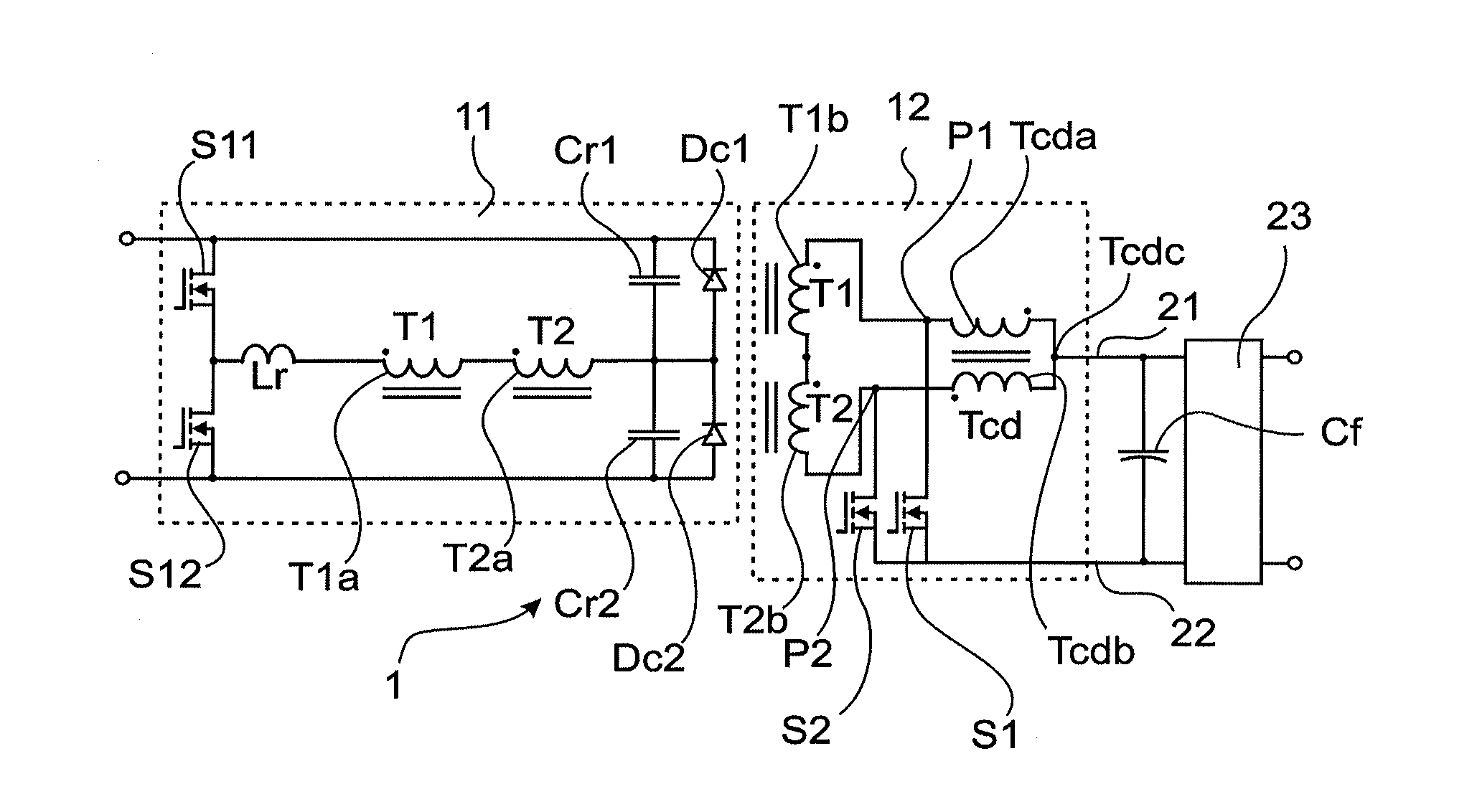
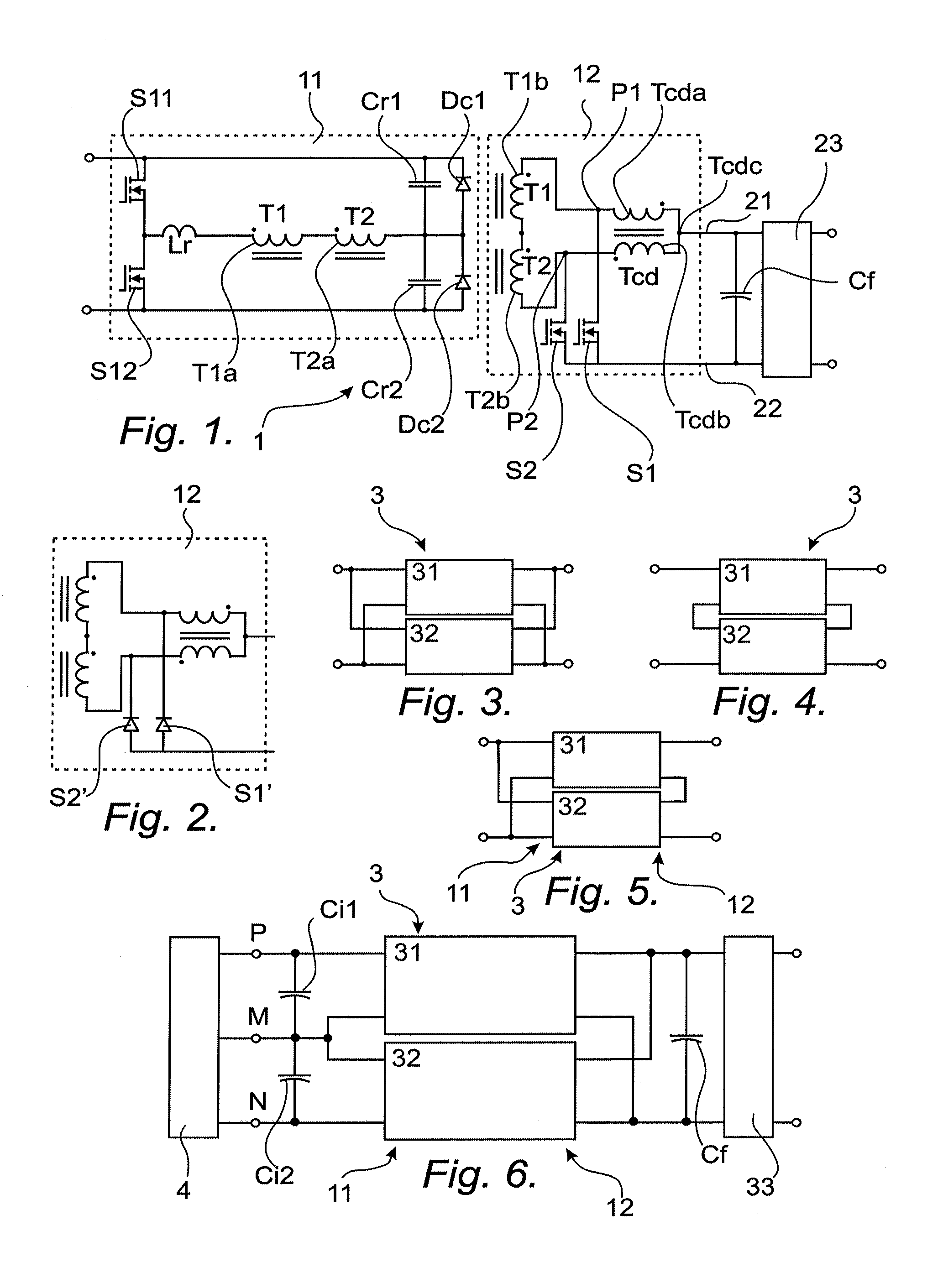
[0052]The present invention will now be described with reference to FIG. 1 showing a DC / DC converter 1 with primary side 11 consisting of a resonant converter, the DC / DC converter 1 comprising at least one transformer, in the following embodiments exemplified by a first and a second transformer T1, T2, connected in series on the primary side 11 and on the secondary side 12 of said DC / DC converter.

[0053]The figure shows schematically the primary winding T1a of the first transformer T1 and the primary winding T2a of the second transformer T2 on the first side 11 of the converter 1. It also shows the secondary winding T1b of the first transformer T1 and the secondary winding T2b of the second transformer T2 on the second side 12 of the converter 1.

[0054]The secondary side 12 of said DC / DC converter 1 comprises an autotransformer Tcd consisting of a first and a second winding Tcda, Tcdb connected to a common centre tap Tcdc. The autotransformer Tcd is adapted to act as a current doubler...


PUM


Abstract

The present invention relates to a DC/DC converter (1) with primary side (11) consisting of a resonant converter, which DC/DC converter (1) comprises a first and a second transformer (T1, T2), connected in series on the primary side (11) and on the secondary side (12) of the DC/DC converter. The secondary side (12) comprises an autotransformer (Tcd) consisting of a first and a second winding (Tcda, Tcdb) connected to a common center tap (Tcdc), where the first winding (Tcda) of the autotransformer (Tcd) is connected to the secondary winding (T1b) of the first transformer (T1), forming a first output connection point (P1), the second winding (Tcdb) of the autotransformer (Tcd) is connected to the secondary winding (T2b) of the second transformer (T2), forming a second output connection point (P2), and the center tap (Tcdc) of the autotransformer (Tcd) is connected to the positive output (21) of the secondary side (12). The secondary side (12) also comprises a first and a second rectifying switching device (S1, S2), where the first rectifying switching device (S1) is connected between the first output connection point (P1) and the negative output (22) of the secondary side (12), and the second rectifying switching device (S2) is connected between the second output connection point (P2) and the negative output (22) of the secondary side (12). The present invention also relates to a DC/DC converter system comprising at least two inventive DC/DC converters (1).

Description

CROSS-REFERENCE TO RELATED APPLICATION[0001]This application is a continuation of International Application No. PCT / CN2010 / 072439, filed on May 4, 2010, which is hereby incorporated by reference in its entirety.FIELD OF INVENTION[0002]The present invention relates to a DC / DC converter with primary side consisting of a resonant converter, which converter comprises at least one transformer, and a converter system comprising at least two inventive DC / DC converters.DESCRIPTION OF BACKGROUND ART[0003]The developing trend of the AC / DC, DC / DC converters is high efficiency and high power density. Through the Resonant AC / DC, DC / DC Converters it is easier to achieve high efficiency due to its feature of soft-switching.[0004]However, there are still certain existing drawbacks regarding the Resonant Converters, e.g., the high AC-current of the output filter resulting in the high power losses and the large volume of the output filter. Furthermore, the center tapped transformer is less efficient ...

Claims


Application Information

Patent Timeline
Patent Type & Authority Applications(United States)
IPC IPC(8): H02M3/335
CPCH02M3/33592H02M3/3376H02M2001/0064Y02B70/1475H02M3/338Y02B70/1433H02M1/0064Y02B70/10
Inventor TORRICO-BASCOPE, GROVER VICTORRUIZ GOMEZ, FERNANDO
Owner HUAWEI TECH CO LTD
Why Eureka
Try Eureka