
Optical fiber

a technology of optical fiber and fiber optics, applied in the field of optical fiber, can solve the problems of reduced water that reaches the optical fiber, insufficient reliability, and severe long-term reliability of the optical fiber cable, and achieve the effect of suppressing the increase in transmission loss and difficult to increase transmission loss

Active Publication Date: 2011-11-10
FURUKAWA ELECTRIC CO LTD
View PDF2 Cites 235 Cited by
  • Summary
  • Abstract
  • Description
  • Claims
  • Application Information

AI Technical Summary

Benefits of technology

[0017]According to the optical fiber of the present invention, an increase in transmission loss can be suppressed when the optical fiber is exposed to water or high humidity by using an optical fiber in which the ratio of thermal expansion coefficient between a coating layer formed by applying a colored layer to an optical fiber and a coating layer of an optical fiber is 0.87 or more. Furthermore, it is possible to provide an optical fiber in which the transmission loss is hard to be increased when the optical fiber is subjected to a use environment or age-related deterioration and in particular, when being exposed to a high humidity by using an optical fiber in which the ratio of thermal expansion coefficient between a coating layer formed by applying a colored layer to an optical fiber and a coating layer of an optical fiber is 0.90 or more.

Problems solved by technology

Therefore, the long-term reliability demanded for the optical fiber cable has become very severe.
However, there are limitations of addressing the above-mentioned problem while keeping the balance of the connectivity of each layer interface, and at present, the optical fiber is put into practical use by combining a configuration in which water is prevented from reaching the optical fiber by further examining the cable structure or cord, or the sheath material and a configuration in which the amount of water that reaches the optical fiber is reduced, and thus its reliability has not been sufficient.

Method used


Image

  • Optical fiber
  • Optical fiber
  • Optical fiber

Examples


examples

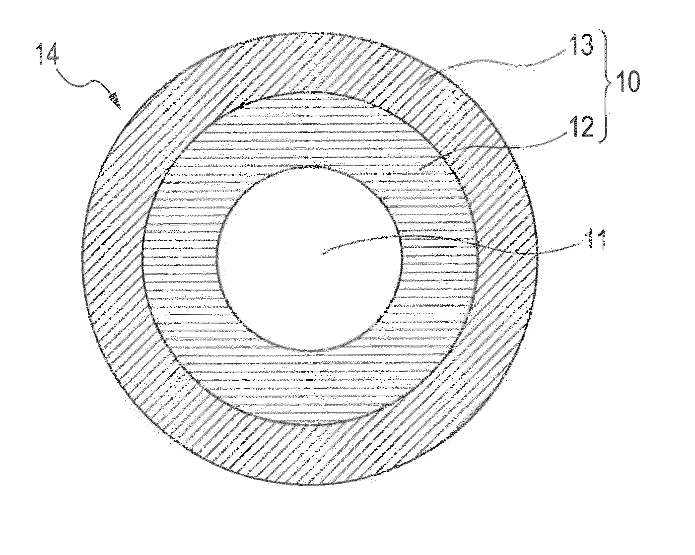
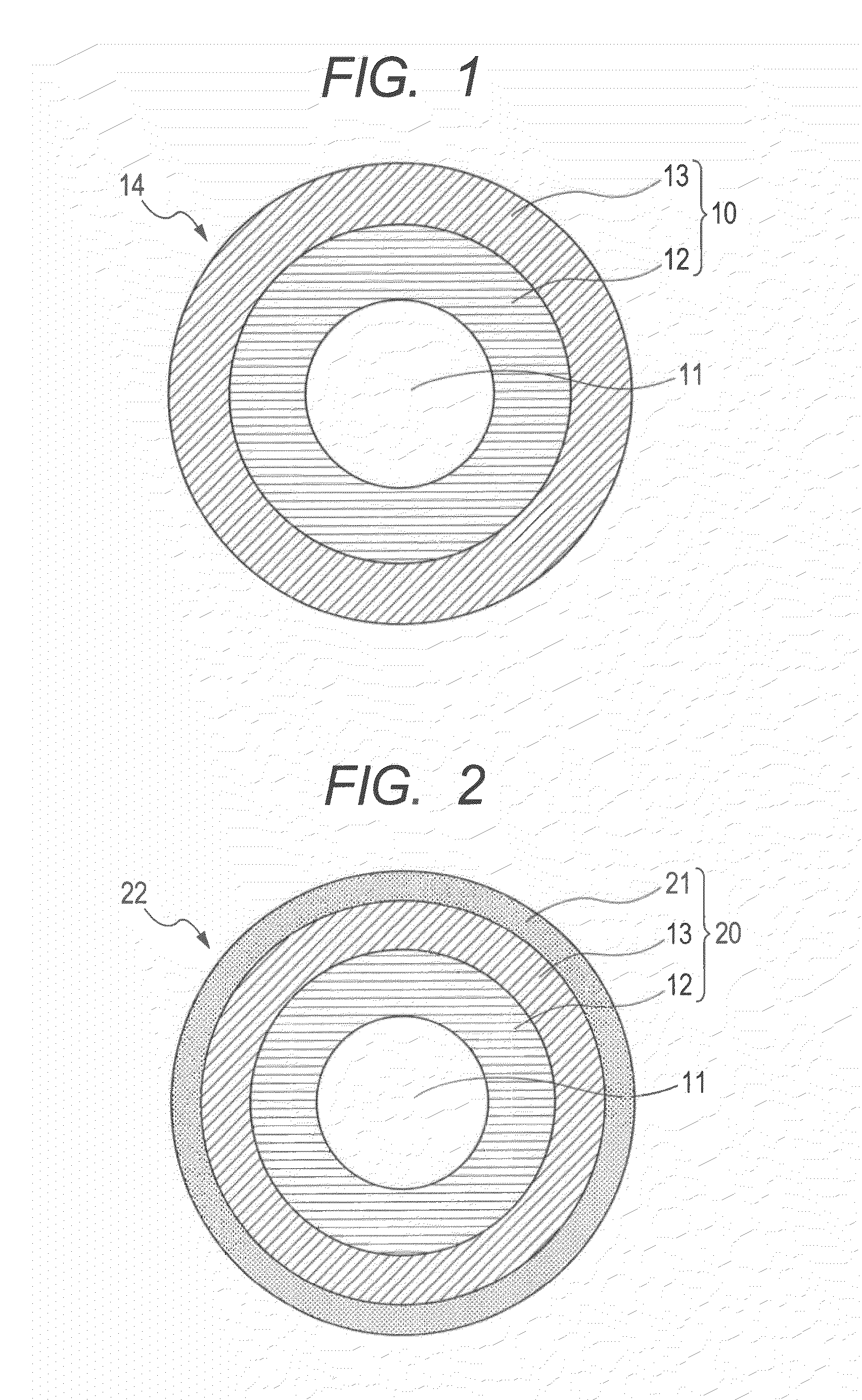
[0025]As shown in FIG. 1, several kinds of the optical fiber 14 were manufactured by coating the glass optical fiber 11 including quartz glass with the double-layered coating resin layer of the primary layer 12 and the secondary layer 13. As each resin, the ultraviolet curing resin was used. The ultraviolet curing resin includes oligomer, diluent monomer, optical initiator, chain transfer agent, and additive agent and the several kinds of the optical fiber 14 are manufactured by varying the component materials.

[0026]The ratio of thermal expansion coefficient between the coating layer after the colored layer is applied to the optical fiber 14 and the coating layer of the optical fiber before the colored layer is applied can be appropriately varied by the skeleton structure and molecular weight of oligomer and / or the kind of diluent monomer to be applied and the amount of application. In general, because of the application of pigment, the ultraviolet curing resin used in the colored l...


PUM


Abstract

The present invention provides an optical fiber in which the transmission loss increase is suppressed even under a high-humidity condition or under a water-immersed condition. A colored optical fiber (22) according to an embodiment of the present invention is a colored optical fiber (22) formed by applying a colored layer to an optical fiber (14) including a glass optical fiber coated with at least a double-layered coating layer of a soft layer and a hard layer, and the ratio of thermal expansion coefficient between the coating layer after the colored layer of the colored optical fiber (22) is applied and the coating layer of the optical fiber (14) before the colored layer is applied is 0.87 or more. Furthermore, an optical fiber ribbon (32) according to another embodiment of the present invention is an optical fiber (32) formed by arranging a plurality of the colored optical fiber (22) in the form of a plane and coating them all together with a ribbon resin and the ratio of thermal expansion coefficient between the coating layer after the colored layer of the colored optical fiber (22) is applied and the coating layer of the optical fiber before the colored layer is applied is 0.90 or more.

Description

CROSS-REFERENCES TO RELATED APPLICATIONS[0001]This application is a continuation application of International Application No. PCT / JP2010 / 067648, filed Oct. 7, 2010, which claims the benefit of Japanese Patent Application No. 2009-286824, filed Dec. 17, 2009. The contents of the aforementioned applications are incorporated herein by reference in their entities.TECHNICAL FIELD[0002]The present invention relates to an optical fiber accommodated within an optical fiber cable. Specifically, the present invention relates to an optical fiber in which an increase in transmission loss of an optical fiber caused by a use environment and age-related deterioration has been suppressed and, more particularly, to an optical fiber in which the transmission loss does not increase for a long period of time even in a high-humidity state or an immersed state or in which the transmission loss has been reduced and water resistance is excellent.BACKGROUND ART[0003]In an optical fiber, a transmission loss ...

Claims


Application Information

Patent Timeline
IPC IPC(8): G02B6/036G02B6/44
CPCG02B6/4403G02B6/02395G02B6/4482
Inventor NAKAJIMA, YASUOMOCHIZUKI, KOUJITANAKA, HIROKIARASHITANI, YOSHIHIRO
Owner FURUKAWA ELECTRIC CO LTD
Learn More