Device for controlling hybrid vehicle
a hybrid vehicle and control device technology, applied in the direction of machines/engines, process and machine control, instruments, etc., can solve the problem of interfering with the execution of intermittent control
- Summary
- Abstract
- Description
- Claims
- Application Information
AI Technical Summary
Benefits of technology
Problems solved by technology
Method used
Image
Examples
first embodiment
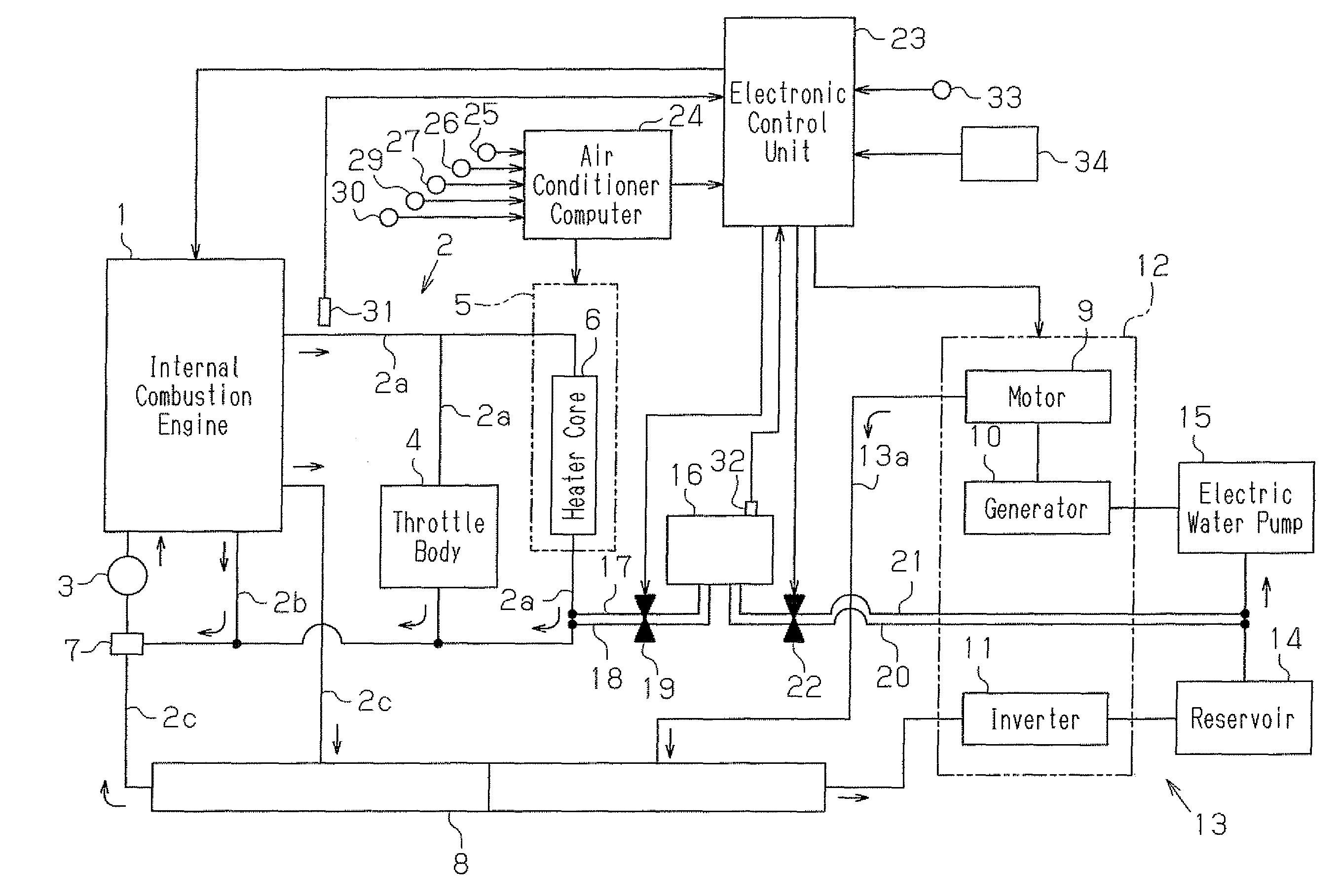
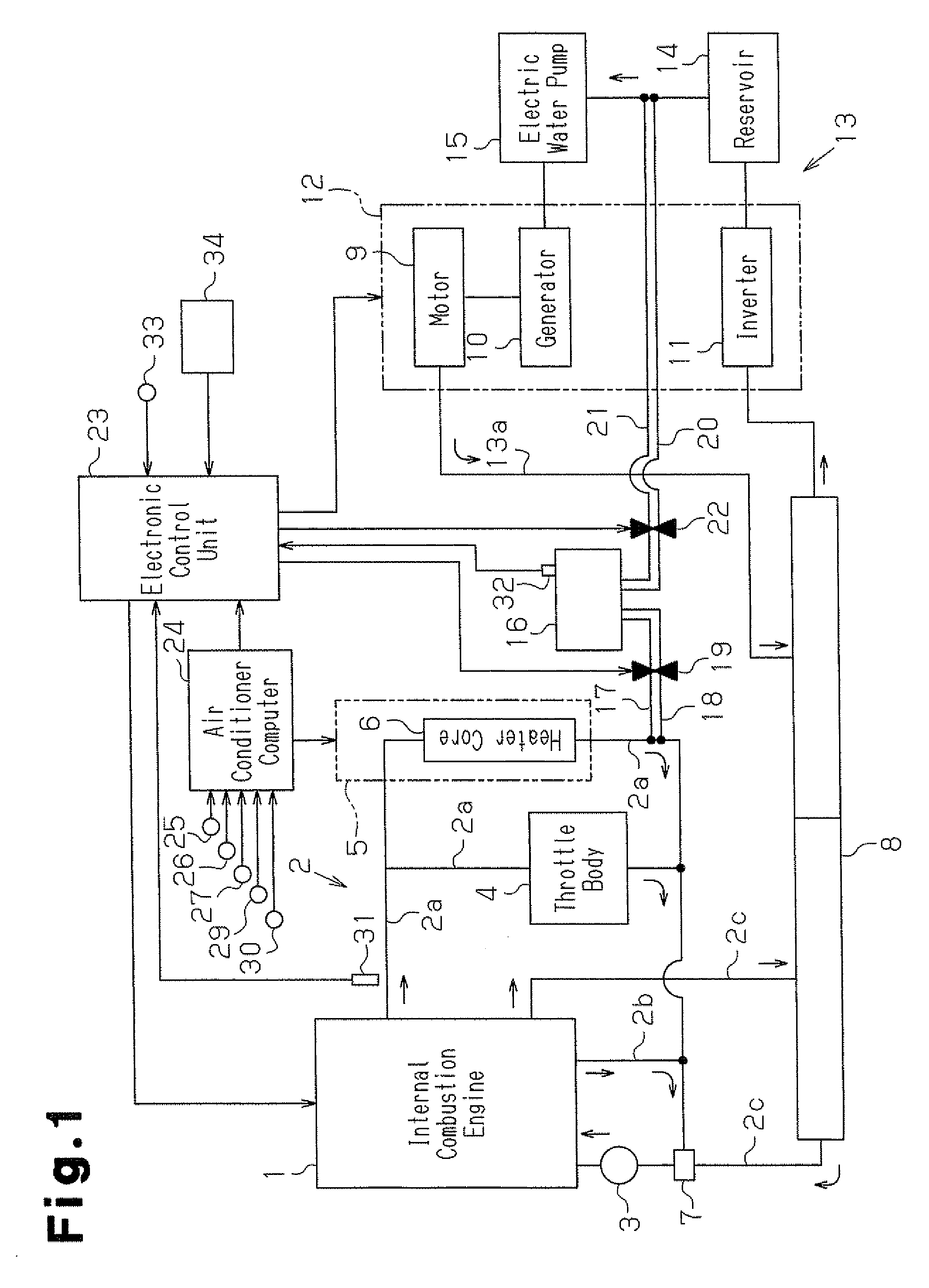
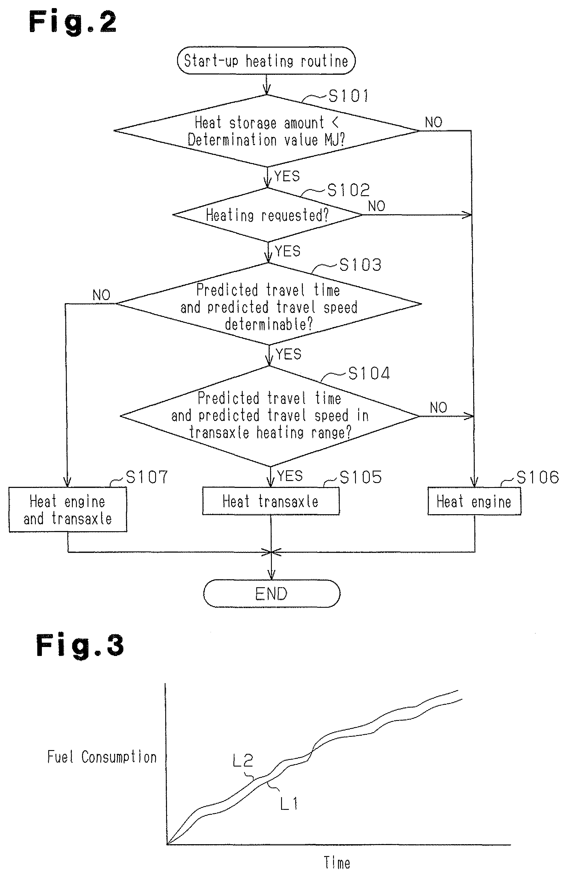
[0046]A first embodiment of the present invention employed in a hybrid vehicle having an internal combustion engine and a motor serving as drive sources will now be described with reference to FIGS. 1 to 5.
[0047]As illustrated in FIG. 1, the hybrid vehicle has a fluid circuit 2 extending through an internal combustion engine 1, which is one of the drive sources. The fluid circuit 2 receives coolant serving as heat exchanging fluid, which is circulated through actuation of a water pump 3. This causes heat exchange between the coolant and the engine 1. Through the heat exchange, the engine 1 is cooled when heated. The water pump 3 is driven through transmission of rotational action from the engine 1.
[0048]The fluid circuit 2 has a passage 2a branched into two sections, one of which is connected to a throttle body 4 with the other connected to a heater core 6 of an air conditioner 5. After exiting the engine 1, some of the coolant flows to the throttle body 4 and the heater core 6 via ...
second embodiment
[0103]A second embodiment of the present invention will hereafter be described with reference to FIGS. 6 and 7.
[0104]In the second embodiment, electric energy produced through actuation of the generator 10 driven by the engine 1 is stored as energy generated through operation of the engine 1. Using the stored electric energy, the engine 1 and the transaxle 12 are heated at subsequent system start-up of the hybrid vehicle.
[0105]As illustrated in FIG. 6, an electrothermal heater 36 is arranged in the passage 2a of the fluid circuit 2 routed through the engine 1. The heater 36 heats coolant in the passage 2a by generating heat using the power supplied from a battery 35. The heater 36 is controlled through the electronic control unit 23. The coolant in the fluid circuit 2 (the passage 2a) is heated by the heater 36 and sent to the engine 1 through the fluid circuit 2. The engine 1 is thus heated by the coolant.
[0106]An electrothermal heater 37 is arranged in the passage 13a of the fluid...
third embodiment
[0117]A third embodiment of the present invention will hereafter be described with reference to FIGS. 8 and 9.
[0118]The third embodiment is different from the first embodiment in that energy produced through operation of the engine 1 after initiation of system start-up in the hybrid vehicle is used to heat the engine 1 and the transaxle 12 when the engine 1 or the transaxle 12 is cold.
[0119]As illustrated in FIG. 8, an inlet passage 38 and an outlet passage 39 are connected to the passage 2a of the fluid circuit 2 routed through the engine 1 and the passage 13a of the fluid circuit 13 routed through the transaxle 12 to allow communication between the passage 2a and the passage 13a. A heating control valve 40 is provided in the inlet passage 38 and the outlet passage 39 and selectively opens and closes to correspondingly permit or prohibit the communication between the passage 2a and the passage 13a. The inlet passage 38, the outlet passage 39, and the heating control valve 40 each f...
PUM
 Abstract
Description
Claims
Application Information
 - R&D
- Intellectual Property
- Life Sciences
- Materials
- Tech Scout
- Unparalleled Data Quality
- Higher Quality Content
- 60% Fewer Hallucinations
Browse by: Latest US Patents, China's latest patents, Technical Efficacy Thesaurus, Application Domain, Technology Topic, Popular Technical Reports.
© 2025 PatSnap. All rights reserved.Legal|Privacy policy|Modern Slavery Act Transparency Statement|Sitemap|About US| Contact US: help@patsnap.com


