Heated Fuel Injector System

Active Publication Date: 2011-11-10
DELPHI TECH IP LTD
View PDF22 Cites 23 Cited by
  • Summary
  • Abstract
  • Description
  • Claims
  • Application Information

AI Technical Summary

Problems solved by technology

Consequently, the open-loop approach may result in less t

Method used


Image

  • Heated Fuel Injector System
  • Heated Fuel Injector System
  • Heated Fuel Injector System

Examples


Embodiment Construction

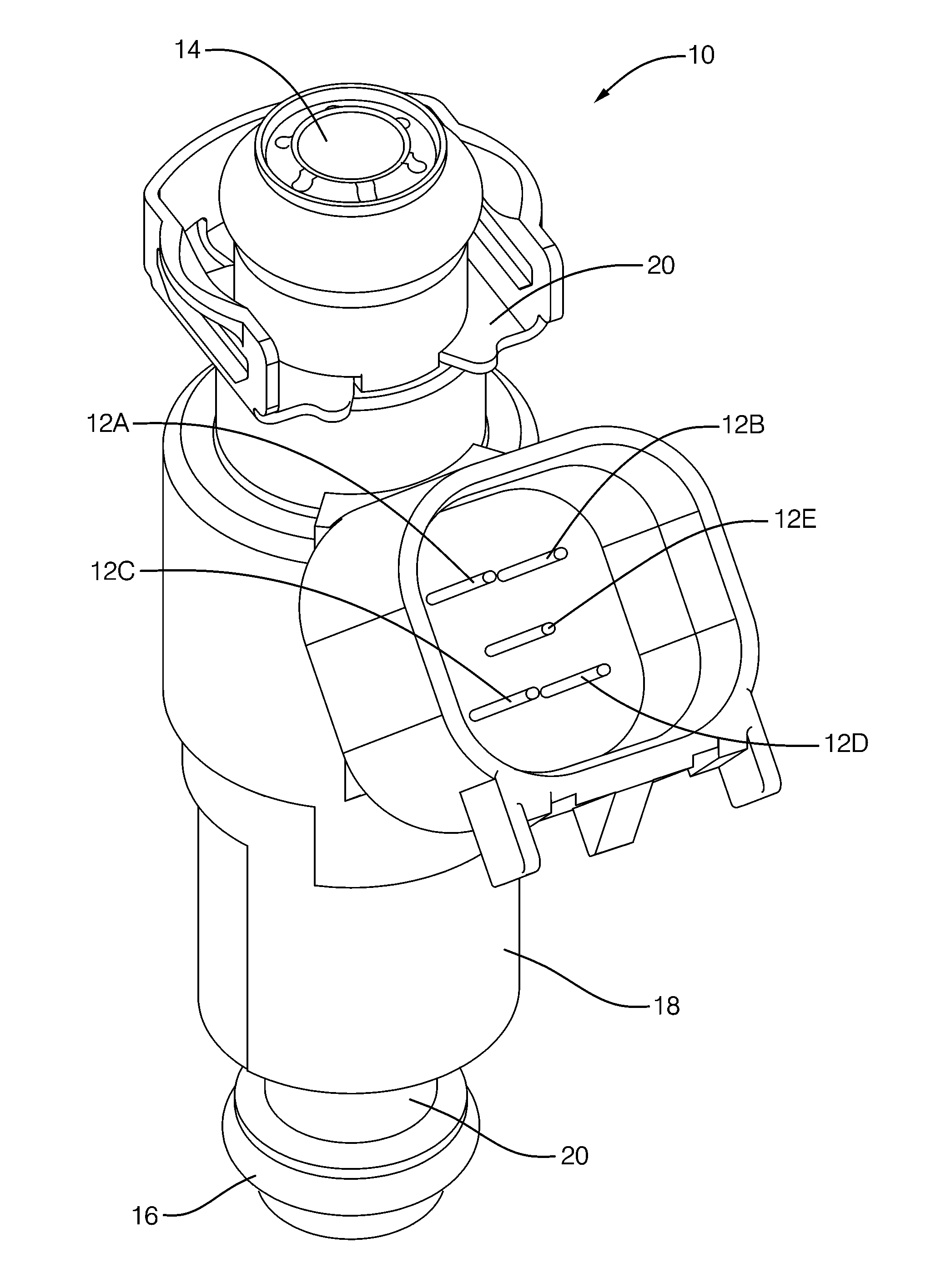
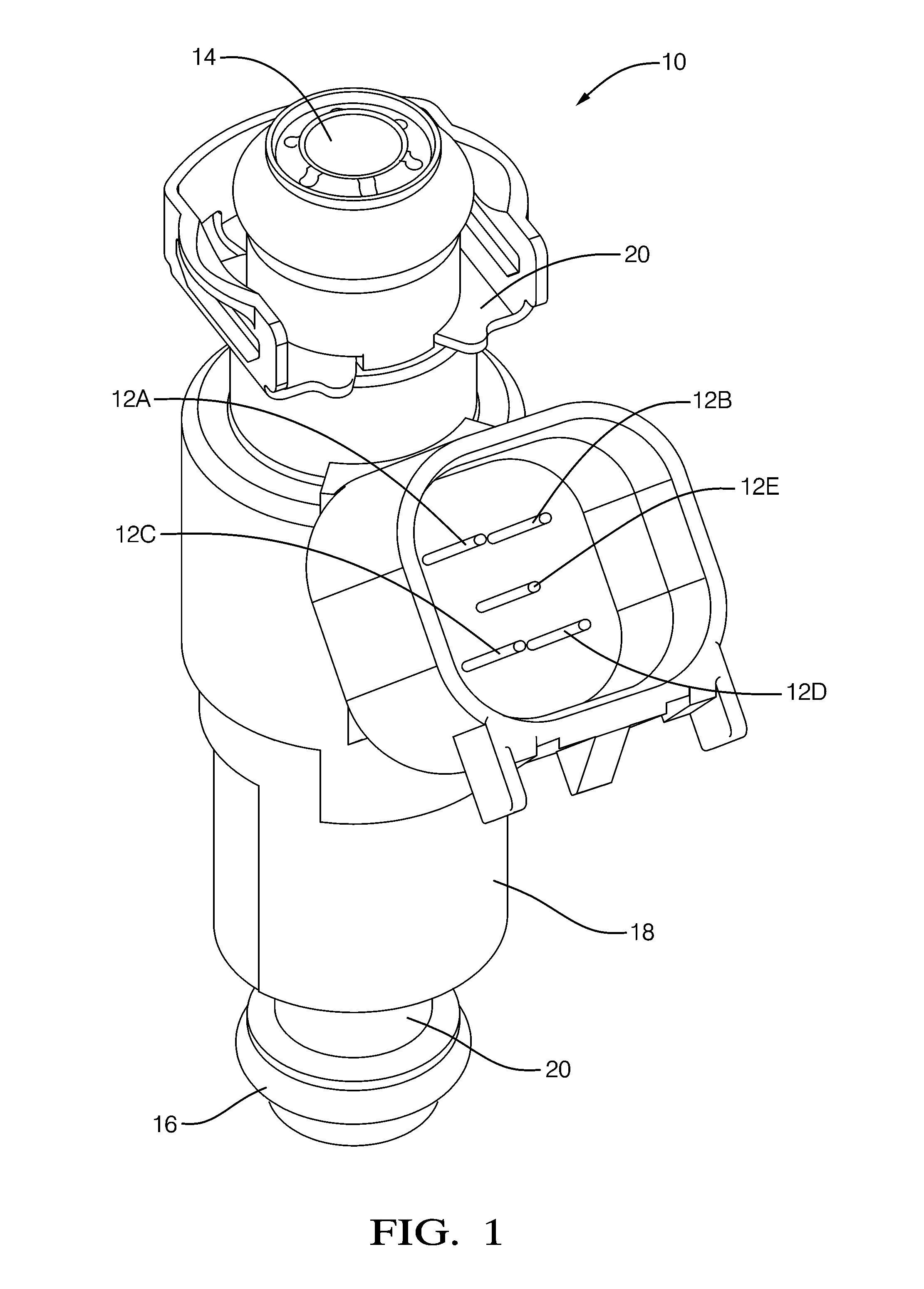
[0016]In accordance with an embodiment of a heated fuel injector system, FIG. 1 illustrates an exemplary heated fuel injector 10 having five connector pins 12a-12e, a fuel inlet end 14, a fuel dispensing end 16, and a shell 18 overlying a fuel injector body 20. Typically, the heated fuel injector 10 would be attached to an internal combustion engine, the fuel inlet end 14 would be coupled to a source of pressurized fuel, and the fuel dispensing end 16 would be positioned so fuel passing through the body 20 would be dispensed by the heated fuel injector 10 to be utilized by the engine to operate the engine. By way of a non-limiting example, connector pins 12a and 12b may be coupled to an actuation coil (not shown) within the body 20 of the heated fuel injector 10 that operates a valve (not shown) also within the body 20 and generally located at the fuel dispensing end 16. Continuing with the example, if a voltage is applied across connector pins 12a and 12b, the valve may open to all...


PUM


Abstract

A heated fuel injector system and controller that includes a temperature sensing means to provide closed-loop control of a heating element heating fuel dispensed by a heated fuel injector. Closed-loop control provides more accurate temperature control of the heating element so that fuel heating is provided as quickly as possible while also protecting the fuel from being boiled and protecting the heated fuel injector from being damaged by excessive temperature. By monitoring how the signal from the temperature sensing means varies over time, fault conditions such as a lack of fuel flow, and fuel ethanol percentage may be detected.

Description

TECHNICAL FIELD OF INVENTION[0001]The invention generally relates to heated fuel injectors, and more particularly relates to a system providing a temperature sensing means to enable closed loop temperature control of fuel dispensed by a heated fuel injector.BACKGROUND OF INVENTION[0002]It is known that heating fuel consumed by an internal combustion engine during a cold start, particularly fuel comprising alcohol, reduced hydrocarbon (HC) and carbon monoxide (CO) emissions. The Society of Automotive Engineers publications entitled Heated Injectors for Ethanol Cold Starts (SAE 2009-01-0615) by Daniel Kabasin et al. and Emission Reduction with Heated Injectors (SAE 2010-01-1265) by Daniel Kabasin et al. document the benefits of using heated fuel injectors to reduce engine emissions, the entire contents of which are hereby incorporated by reference herein. The temperature control of such heated injectors typically uses an open loop approach that regulates power to a heater element base...

Claims


Application Information

Patent Timeline
IPC IPC(8): F02D41/30G01K13/00B05B1/24
CPCF02M53/06
Inventor KABASIN, DANIEL FRANCISVOLPATO, ORLANDOALLSTON, BRIAN KEITHIANNONE, CHARLES ANTHONY
Owner DELPHI TECH IP LTD
Why Eureka
Try Eureka