Temperature controller, fluid circulator and temperature control method using temperature controller

Inactive Publication Date: 2011-11-17
KELK LTD
View PDF16 Cites 4 Cited by
  • Summary
  • Abstract
  • Description
  • Claims
  • Application Information

AI Technical Summary

Benefits of technology

[0012]An object of the invention is to provide a temperature controller and a fluid circulator that are compactible in their entirety and reducible in manufacturing c

Problems solved by technology

Consequently, the flow-rate control valve can be down-sized

Method used


Image

  • Temperature controller, fluid circulator and temperature control method using temperature controller
  • Temperature controller, fluid circulator and temperature control method using temperature controller
  • Temperature controller, fluid circulator and temperature control method using temperature controller

Examples


Embodiment Construction

)

[0031]Exemplary embodiment(s) of the invention will be described below with reference to the attached drawings.

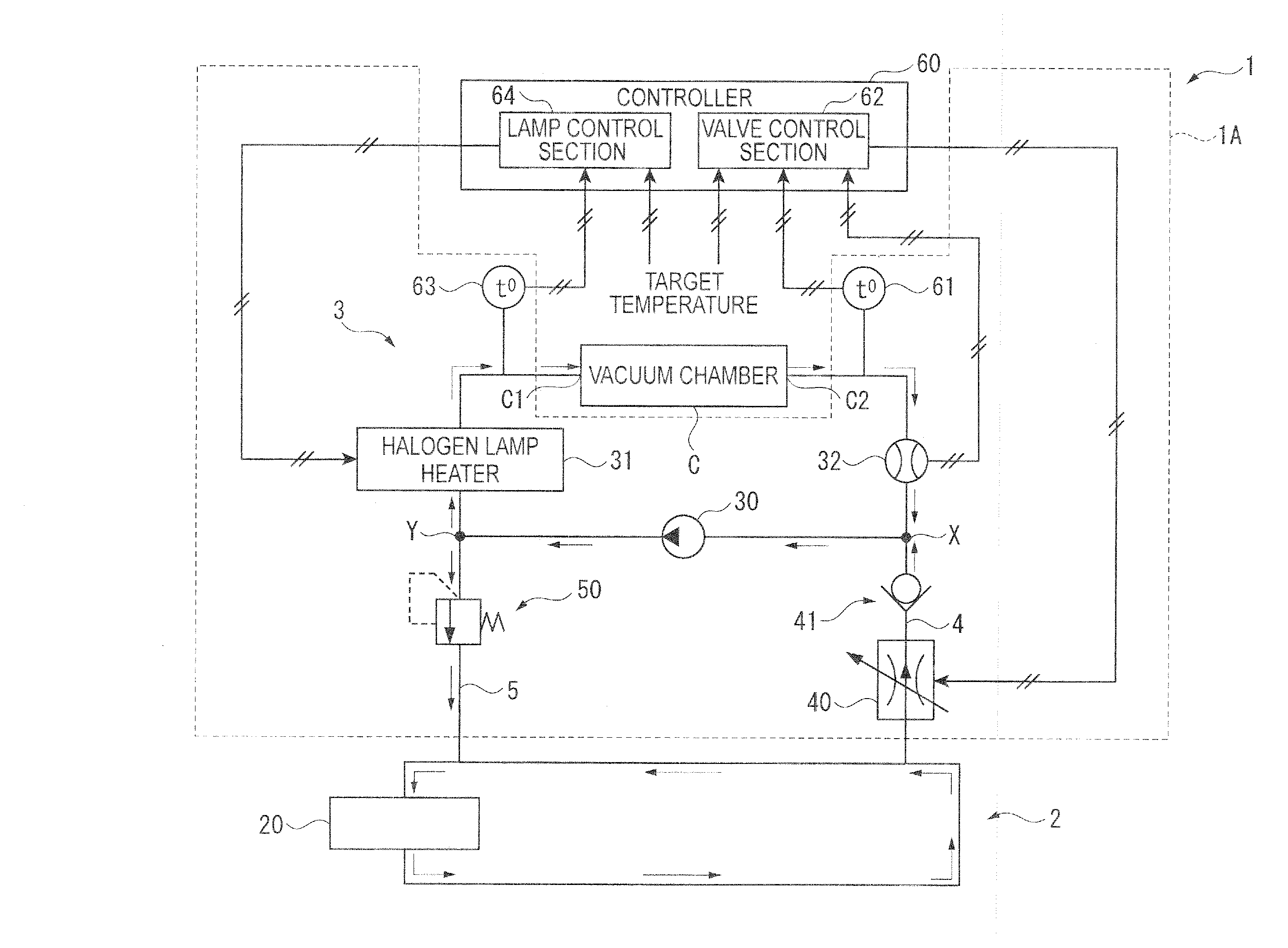
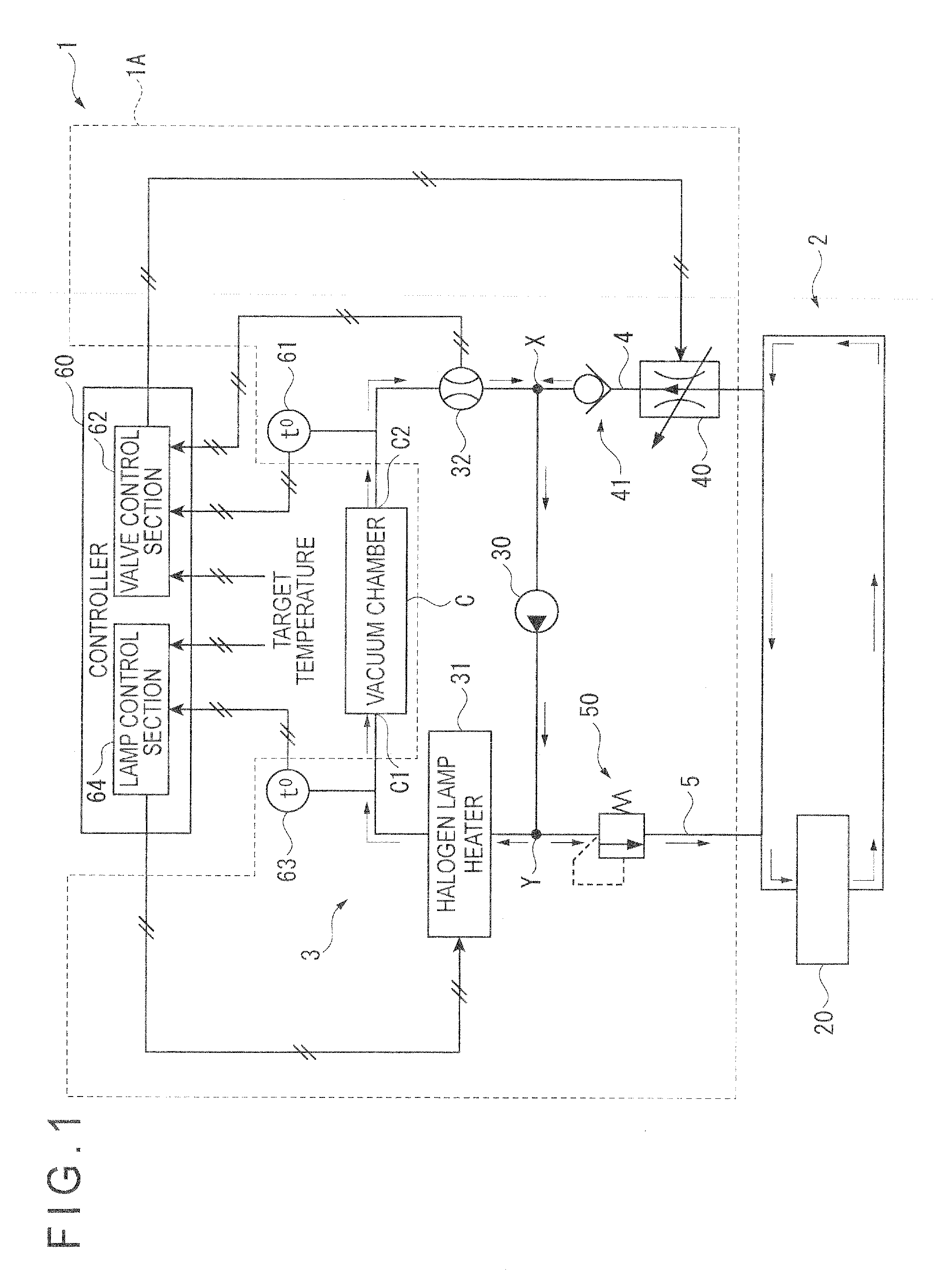
[0032]As shown in FIG. 1, a temperature controller 1 includes: a closed first circulation circuit 2; a closed second circulation circuit 3; a feed path 4 that feeds a thermal fluid from the first circulation circuit 2 to the second circulation circuit 3; a discharge path 5 that discharges the thermal fluid from the second circulation circuit 3 and returns the thermal fluid to the first circulation circuit 2; and a controller 60 provided with a valve control section 62 and a lamp control section 64. The temperature controller 1 circulates and feeds the thermal fluid adjusted to a predetermined target temperature Sv to a vacuum chamber C (an object to be temperature-controlled) and controls a temperature of the vacuum chamber C by means of the circulated and fed thermal fluid.

[0033]As shown in FIG. 1 in a dotted line, the second circulation circuit 3, the feed path 4 and the...


PUM


Abstract

A temperature controller includes: a closed first circulation circuit having a fluid cooler; a closed second circulation circuit having a halogen lamp heater as a fluid heater and feeding a thermal fluid heated by the halogen lamp heater to a vacuum chamber as an object to be temperature-controlled; a feed path that feeds the thermal fluid from the first circulation circuit to the second circulation circuit; and a discharge path that discharges the thermal fluid from the second circulation circuit and returns the thermal fluid to the first circulation circuit. A flow-rate control valve that adjusts and controls a feed flow-rate of the thermal fluid from the first circulation circuit is provided in the feed path. A pressure control valve that compensates a pressure of the thermal fluid at a predetermined pressure level or less is provided in the discharge path.

Description

[0001]The entire disclosure of Japanese Patent Application No. 2010-110913 filed May 13, 2010 is expressly incorporated by reference herein.BACKGROUND OF THE INVENTION[0002]1. Field of the Invention[0003]The present invention relates to a temperature controller for controlling a temperature of an object to be temperature-controlled, a fluid circulator for circulating and feeding a thermal fluid adjusted to a predetermined temperature to the object, and a temperature control method using the temperature controller.[0004]2. Description of Related Art[0005]Typically, a semiconductor wafer is subjected to various semiconductor treatment such as plasma etching treatment using plasma heat. Such various semiconductor treatment are generally performed by circulating and feeding a thermal fluid adjusted to a predetermined target temperature to an object to be temperature-controlled such as a vacuum chamber, and controlling a temperature of the object by means of the circulated and fed therma...

Claims


Application Information

Patent Timeline
IPC IPC(8): F28F27/00F15D1/00F28D15/00
CPCH01L21/67248G05D23/1931Y10T137/6416G05D23/00H01L21/00
Inventor TAKAHASHI, NORIO
Owner KELK LTD
Why Eureka
Try Eureka