Rotor for electric rotating machine

Active Publication Date: 2011-11-17
DENSO CORP
View PDF8 Cites 14 Cited by
  • Summary
  • Abstract
  • Description
  • Claims
  • Application Information

AI Technical Summary

Benefits of technology

[0018]With the openings, the magnetic reluctance at the circumferentially-central portions of the magnetic poles is increased, thereby securing a large reluctance torque of the electric rotating machine. Moreover, with the symmetrically arranged reinforcing portions, the mechanical strength of the rotor core is enhanced. Consequently, during rotation of the rotor, it is possible to prevent the radially-outer peripheral portions of the rotor core from being moved radially outward by the centrifugal force, thereby making it possible to keep a

Problems solved by technology

However, in this case, the strength of the rotor core 22 would be accordingly reduced, thereby making

Method used


Image

  • Rotor for electric rotating machine
  • Rotor for electric rotating machine
  • Rotor for electric rotating machine

Examples


Embodiment Construction

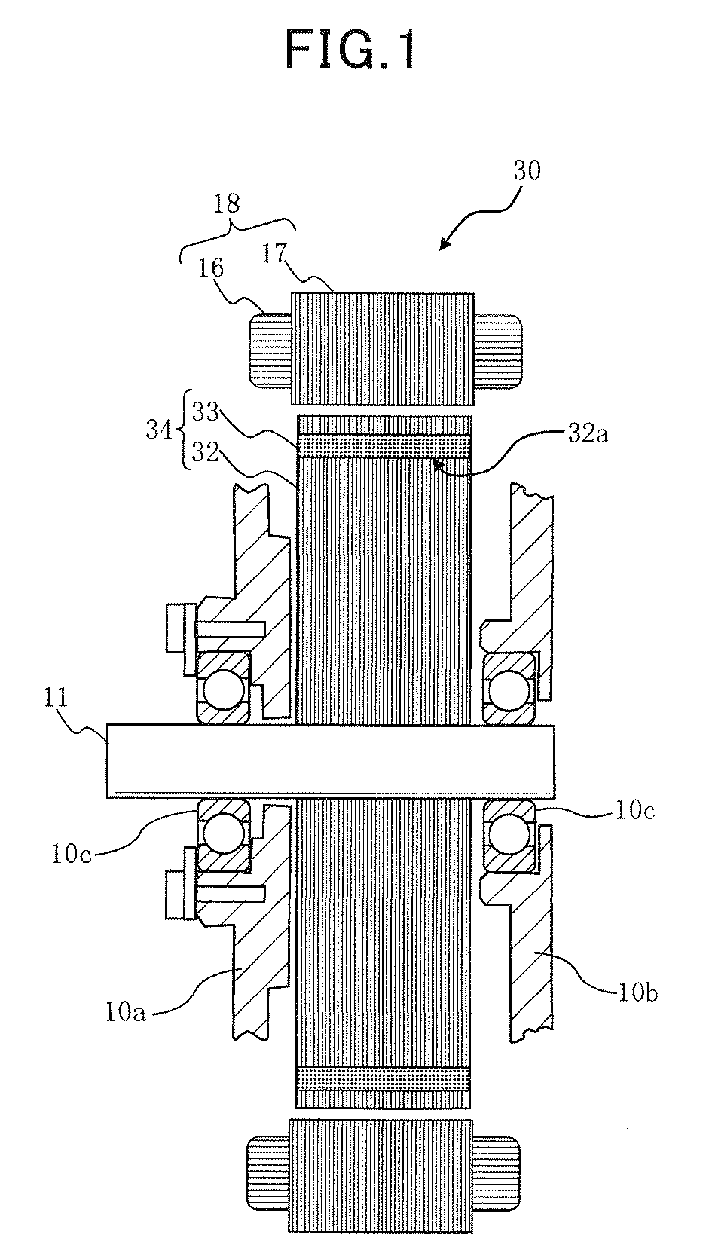
[0038]FIG. 1 shows the overall configuration of an electric rotating machine 30 which includes a rotor 34 according to an embodiment of the invention. The electric rotating machine 30 is configured to function, for example, as an electric motor in a hybrid or electric vehicle.

[0039]As shown in FIG. 1, the electric rotating machine 30 includes: a pair of front and rear housings 10a and 10b (only partially shown) that are fixed together by means of a plurality of bolts (not shown) and have a pair of bearings 10c respectively arranged therein; a rotating shaft 11 that is rotatably supported by the front and rear housings 10a and 10b via the pair of bearings 10c; the rotor 34 that is fixed on the rotating shaft 11 and received in the front and rear housings 10a and 10b; and a stator 18 that is held between the front and rear housings 10a and 10b and disposed radially outside and coaxially with the rotor 34. In addition, in the present embodiment, the stator 18 functions as an armature w...


PUM


Abstract

A rotor includes a hollow cylindrical rotor core and permanent magnets embedded in the rotor core to form a plurality of magnetic poles on the radially outer periphery of the rotor core. The rotor core has a plurality of openings each of which extends in the axial direction of the rotor core so as to penetrate it. When viewed along the axial direction, each of the openings is symmetrically positioned with respect to the centerline of a corresponding one of the magnetic poles. For each of the openings, there are provided n reinforcing portions, where n is an integer not less than 2. The n reinforcing portions extend to connect a pair of radially-inner and radially-outer peripheral portions of the rotor core, thereby partitioning the opening into (n+1) parts. The n reinforcing portions are symmetrically arranged with respect to the centerline of the corresponding magnetic pole.

Description

CROSS-REFERENCE TO RELATED APPLICATIONS[0001]This application is based on and claims priority from Japanese Patent Applications No. 2010-110286 filed on May 12, 2010 and No. 2011-89116 filed on Apr. 13, 2011, the contents of which are hereby incorporated by reference in their entireties into this application.BACKGROUND[0002]1. Technical Field[0003]The present invention relates to rotors for electric rotating machines that are used in, for example, motor vehicles as electric motors and electric generators.[0004]2. Description of Related Art[0005]Interior Permanent Magnet (IPM) motors, such as the one disclosed in Japanese Patent Application Publication No. 2006-254599, generally have a plurality of permanent magnets embedded in a rotor core thereof along the circumferential direction of the rotor core.[0006]FIG. 9 shows the overall configuration of a conventional IPM motor 10. As shown in the figure, the motor 10 includes a rotating shaft 11, a rotor 14 and a stator 18.[0007]The roto...

Claims


Application Information

Patent Timeline
IPC IPC(8): H02K1/27
CPCH02K1/2766
Inventor UTAKA, RYOSUKE
Owner DENSO CORP
Why Eureka
Try Eureka