Eureka AIR delivers breakthrough ideas for toughest innovation challenges, trusted by R&D personnel around the world.

Variable load line gas curve intercept method to optimize system efficiency

Inactive Publication Date: 2011-11-17
ROBERTSON TRANSFORMER
View PDF7 Cites 2 Cited by
  • Summary
  • Abstract
  • Description
  • Claims
  • Application Information

AI Technical Summary

Benefits of technology

[0012]A first aspect of the present invention is directed to a method of controlling and regulating a power supply attached to a non-linear plasma load. The method comprises the steps of: utilizing a multi-parametric load line intercept control of a series source impedance; sequencing of a voltage and a frequency control; allowing a highly dynamic gas plasma load curve to be tracked through a load dynamic without a loss of conduction or plasma stability; and shaping of an initial current, as a load is energized during a conduction cycle, wherein a means of feedback is provided as to the appropriateness and quality of the adjustment.

Problems solved by technology

Gas-discharge lamps offer long life and high light efficiency, but are more complicated to manufacture, and they require electronics to provide the correct current flow through the gas.
Once the arc is started, it heats and evaporates the metal salts forming a plasma, which greatly increases the intensity of light produced by the arc and reduces its power consumption.
The highest wear occurs when the HID burner is ignited while still hot and before the metallic salts have recrystallized.
As they heat up during operation, however, the internal gas pressure within the arc tube rises and a higher voltage is required to maintain the arc discharge.
As the lamp heats to this point, the arc fails and the lamp goes out.
Eventually, with the arc extinguished, the lamp cools down again, the gas pressure in the arc tube is reduced, and the ballast can once again cause the arc to strike.

Method used


Image

  • Variable load line gas curve intercept method to optimize system efficiency
  • Variable load line gas curve intercept method to optimize system efficiency
  • Variable load line gas curve intercept method to optimize system efficiency

Examples


Embodiment Construction

[0031]While this invention is susceptible of embodiments in many different forms, there is shown in the drawings and will herein be described in detail preferred embodiments of the invention with the understanding that the present disclosure is to be considered as an exemplification of the principles of the invention and is not intended to limit the broad aspect of the invention to the embodiments illustrated.

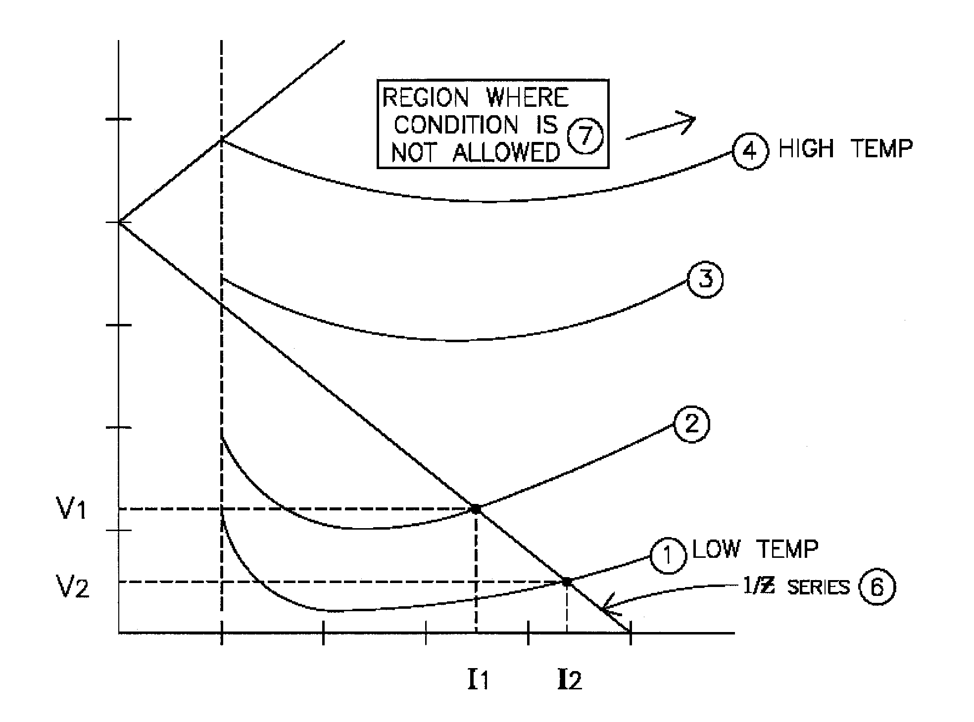
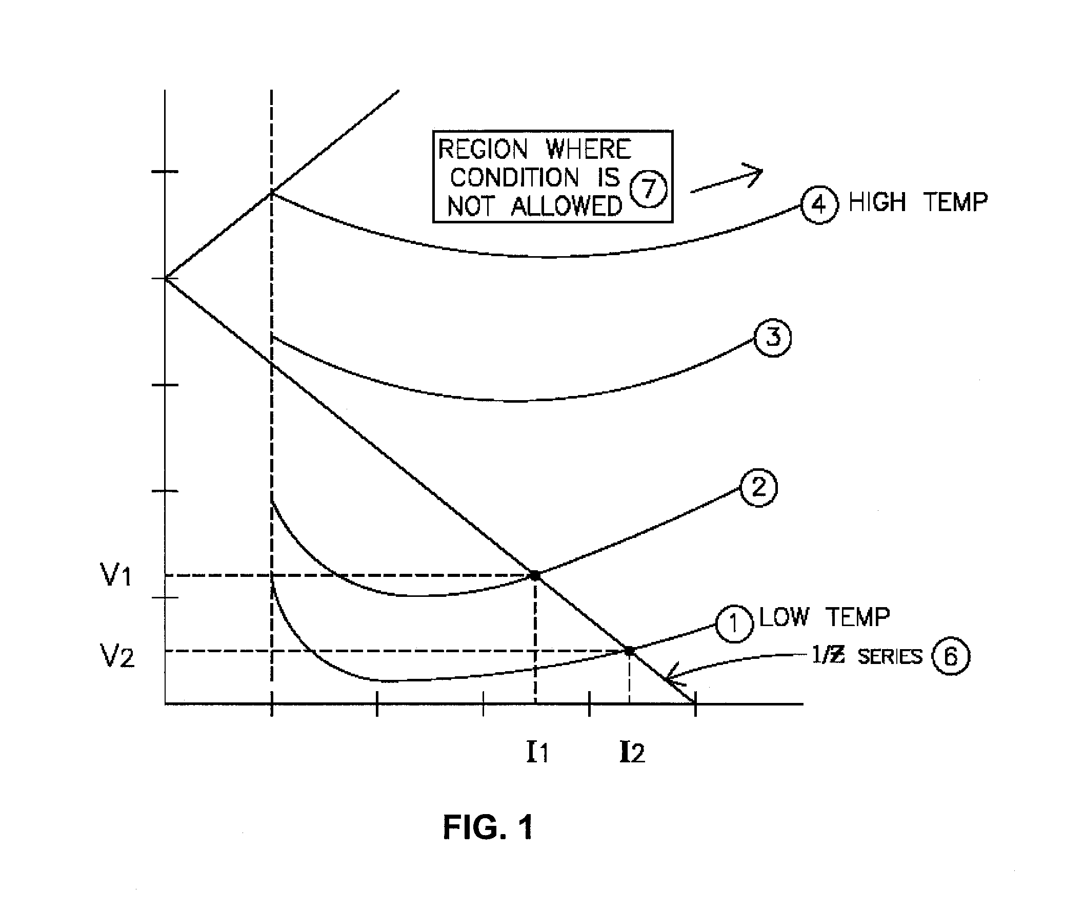
[0032]The present invention addresses an approach to the operation and stabilization of gas plasma loads. This is accomplished by sensing how fast the plasma goes in conduction as it goes through a zero cross point of the cyclic load driving voltage. A period Tsample area just after the zero cross would ideally behave like a pure resistance, and thus it would follow the voltage precisely. When the plasma approaches a condition that is near extinguishing, the current at low voltage such as that near the zero cross point will increase very little at first and then quickly increas...


PUM


Abstract

The operation of gas discharge devices involves stabilizing drive stage with a highly dynamic load exhibiting both negative resistance and non-linear behavior. Stabilization is typically accomplished by inserting impedance in series with the plasma load so the combination impedance has a voltage division that is characterized by the intersection of the linear series impedance and the instantaneous voltage-current. This is stable as long as there is an ample excess of voltage driving the plasma / series impedance complex. However providing series impedance that insures stable operation over varying power levels, lamp types / chemistries and changes resulting from aging can lead to inefficient operation as a result of either high voltage / power drops in the series impedance or a high source voltage driving smaller impedance. A method to optimize the series impedance and driving voltage through a dynamic adjustment process of both the voltage and impedance parameters to provide stable gas plasma drive and maximize system efficiency is described.

Description

CROSS-REFERENCE TO RELATED APPLICATION[0001]The present invention claims the benefit of U.S. Provisional Patent Application No. 61 / 138,770 filed Dec. 18, 2008, the contents of which are incorporated herein by reference.TECHNICAL FIELD[0002]The present invention is related to improving efficiency of lighting fixtures. More particularly, the present invention is related to a method of improving efficiency of lighting fixtures using a variable load line gas curve intercept method.BACKGROUND OF THE INVENTION[0003]Gas-discharge lamps are a family of artificial light sources that generate light by sending an electrical discharge through an ionized gas, i.e. a plasma, in a transparent tube. The character of the gas discharge critically depends on the frequency or modulation of the current. Typically, such lamps use a noble gas (argon, neon, krypton and xenon) or a mixture of these gases. Most lamps are filled with additional materials, like mercury, sodium, and / or metal halides. In operati...

Claims


Application Information

Patent Timeline
IPC IPC(8): H05B41/16
CPCB60Q11/005Y02B20/22H05B41/38Y02B20/00
Inventor BEASLEY, DENNY D.
Owner ROBERTSON TRANSFORMER
Why Eureka
Eureka Blog
Learn More