Centrifugal Blower with Partitioned Scroll Diffuser

a diffuser and centrifugal blower technology, applied in the direction of positive displacement liquid engines, piston pumps, liquid fuel engines, etc., can solve the problems of adverse effects on the efficiency of the impeller assembly, and achieve the effects of reducing noise generation, simple design, and optimizing flow and pressure characteristics

Active Publication Date: 2011-11-17
LTI HLDG INC
View PDF3 Cites 9 Cited by
  • Summary
  • Abstract
  • Description
  • Claims
  • Application Information

AI Technical Summary

Benefits of technology

[0008]Benefits to the designer include allowing for variations in size and position of each housing discharge opening as the system application may require. Further, each scroll diffuser section may be designed to optimize the flow and pressure characteristics of the particular system flow

Problems solved by technology

One of the challenges for a designer of centrifugal blowers is to provide a scroll diffuser which efficiently converts velocity pressure to static pressure and at the same time aligns discharge flow accurate

Method used


Image

  • Centrifugal Blower with Partitioned Scroll Diffuser
  • Centrifugal Blower with Partitioned Scroll Diffuser
  • Centrifugal Blower with Partitioned Scroll Diffuser

Examples


Embodiment Construction

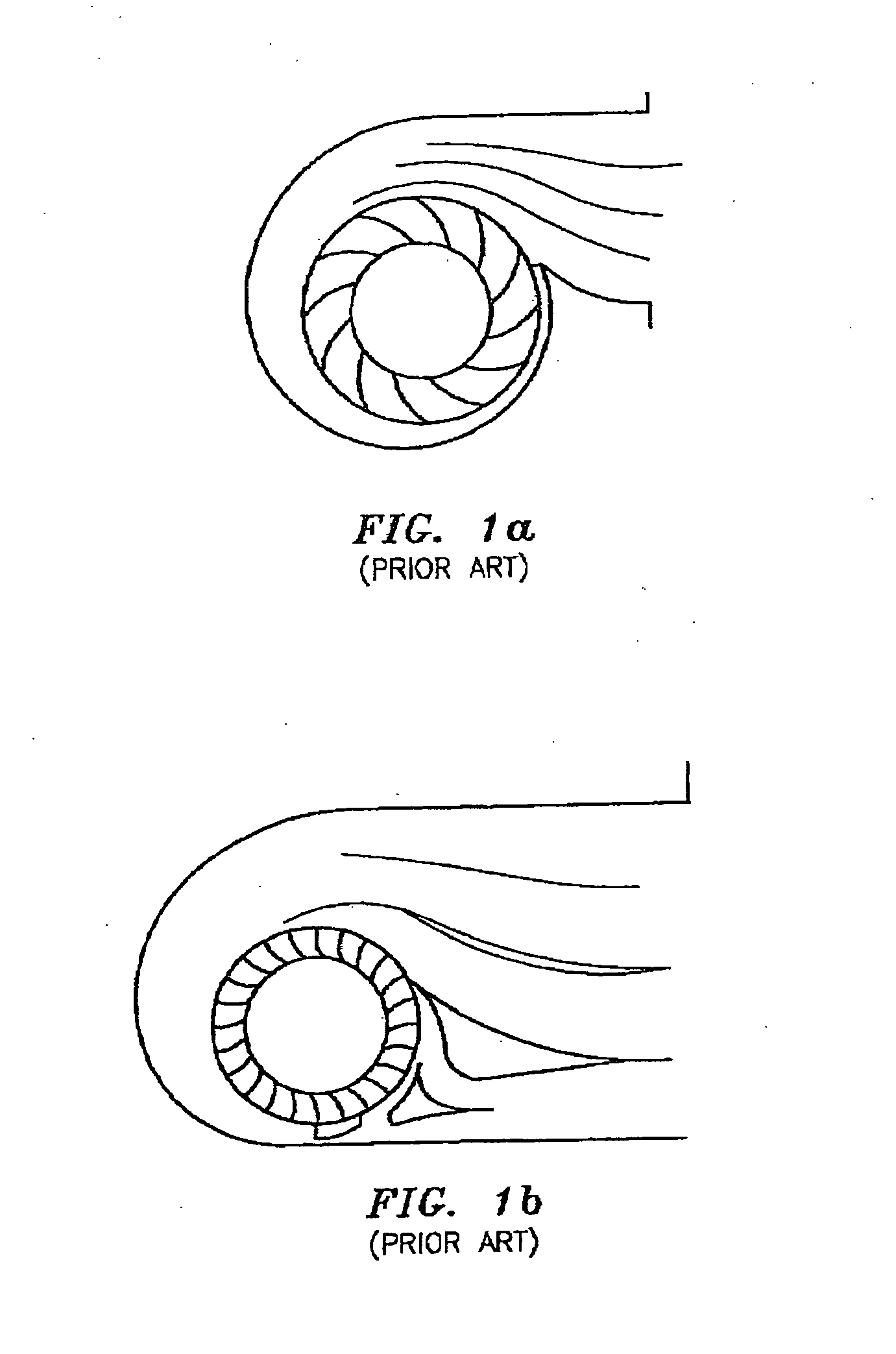
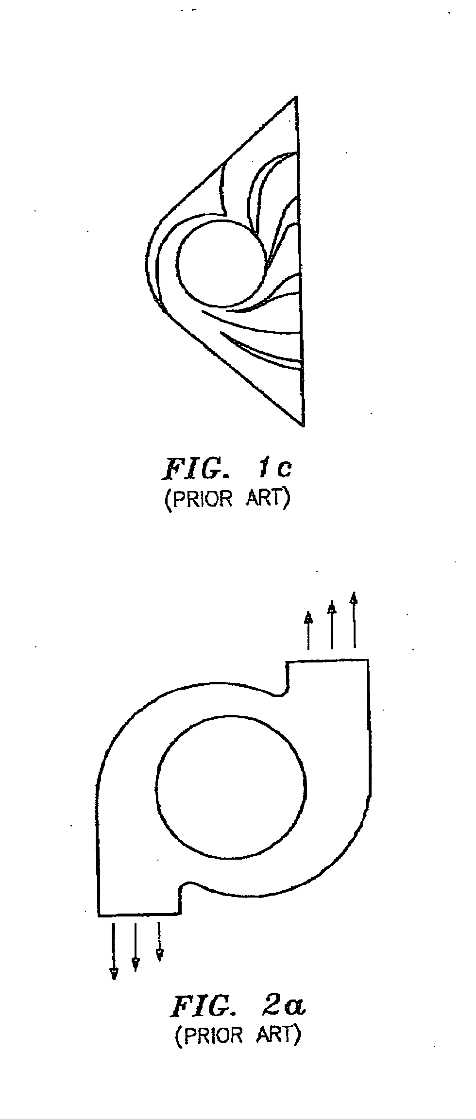
[0025]FIGS. 1a through 2b illustrate various prior art designs employed in providing broad band and other discharge flow patterns primarily through the use of a plurality of vanes mounted in the scroll diffuser outlet section.

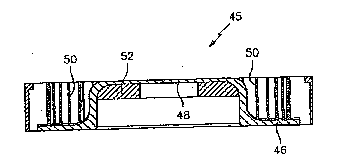
[0026]Referring particularly to FIG. 3, a centrifugal blower in accordance with the invention and indicated generally at 10 includes an impeller 12 which may take a conventional form and which receives inlet air axially through an opening 14 in an upper scroll sub-section 18. Upper and lower scroll sub-sections 18 and 20 are partially shown at the left-hand portion of the drawing. The scroll may be of metal or thermoplastic construction and includes a radial plane partition 22 mounted therewithin and which has a central opening 24 closely surrounding the periphery of the impeller 12.

[0027]In accordance with the invention, the sub-sections 18 and 20 of the scroll are separated by the partition 22 and as illustrated in FIG. 5 are wholly independent of each other....


PUM


Abstract

A centrifugal blower having at least one radial plane dividing its scroll into sub-sections which may vary as to cut-off points and axial and radial dimensions as well as axial displacement to meet requirements of individual application system flow paths.

Description

CROSS-REFERENCE TO RELATED APPLICATIONS[0001]This is a continuation application of U.S. patent application Ser. No. 10 / 080,200 filed on Feb. 19, 2002 and entitled CENTRIFUGAL BLOWER WITH PARTITIONED SCROLL DIFFUSER, which itself claims priority from U.S. Provisional Application 60 / 270,932 filed on Feb. 26, 2001 and entitled CENTRIFUGAL BLOWER WITH PARTITIONED SCROLL DIFFUSER, the contents of which being incorporated herein in their entirety.BACKGROUND OF THE INVENTION[0002]This invention relates to a partitioned scroll diffuser, designed to efficiently provide multiple flow paths from a single centrifugal impeller.[0003]One of the challenges for a designer of centrifugal blowers is to provide a scroll diffuser which efficiently converts velocity pressure to static pressure and at the same time aligns discharge flow accurately with the system flow paths required in a particular application of the blower. Efficient alignment of the discharge flow with the required system flow paths is...

Claims


Application Information

Patent Timeline
IPC IPC(8): F04B35/04F04D29/42
CPCF04D29/4246
Inventor O'CONNOR, JR., JOHN F.DICKINSON, ROGER B.
Owner LTI HLDG INC
Why Eureka
Try Eureka