

Systems, devices and methods for providing energy for ship propulsion
a technology of propulsion system and energy supply, applied in the field of systems, can solve the problems of large and generally inefficient propulsion system, and achieve the effect of less air pollution and less fossil fuel requirements
- Summary
- Abstract
- Description
- Claims
- Application Information
AI Technical Summary
Benefits of technology
Problems solved by technology
Method used
Image

Examples
first embodiment
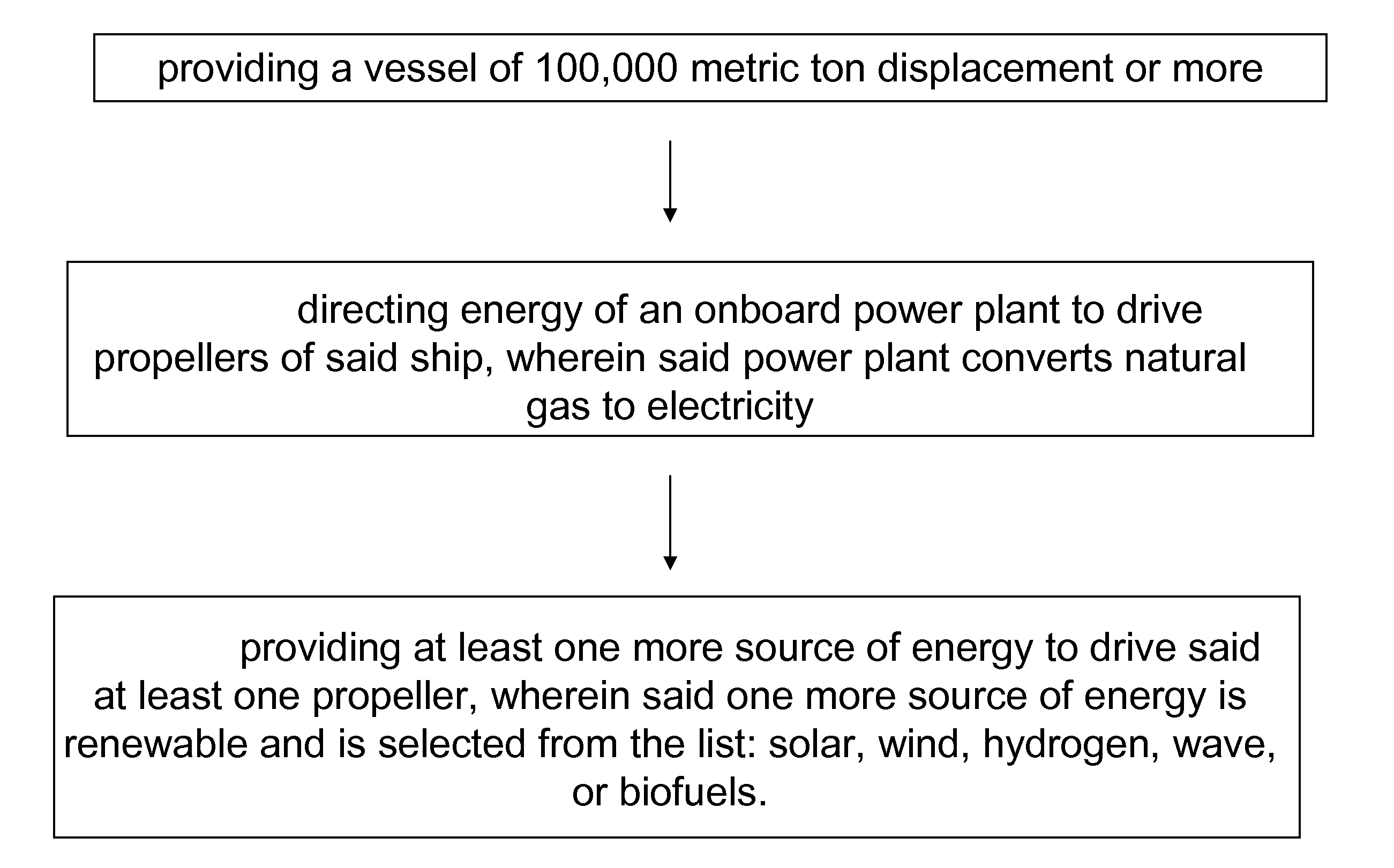
[0049]Attention is turned to FIG. 1, which shows a schematic embodiment of the present invention. Vessel 102 includes a power plant 105 which is connected 107 to the drive shaft 109 of a propeller 110. To note, the present invention retains propeller-based ship propulsion and changes the source of energy used for driving said propeller 110. Instead of a diesel-based system which would require engine, all supporting machinery and equipment, as well as tens to hundreds of thousands of gallons of fuel, the present invention would make use of a power plant 105 and its associated fuel, which may include natural gas or possibly renewable energy sources (not shown). The present invention is based in part in the fact that in many seafaring applications, a ship either travels between points or engages in a particular activity. For example, a desalination ship may travel hundreds of kilometres to a point where it begins to work. At that location, the ship drops anchor and begins converting se...
second embodiment
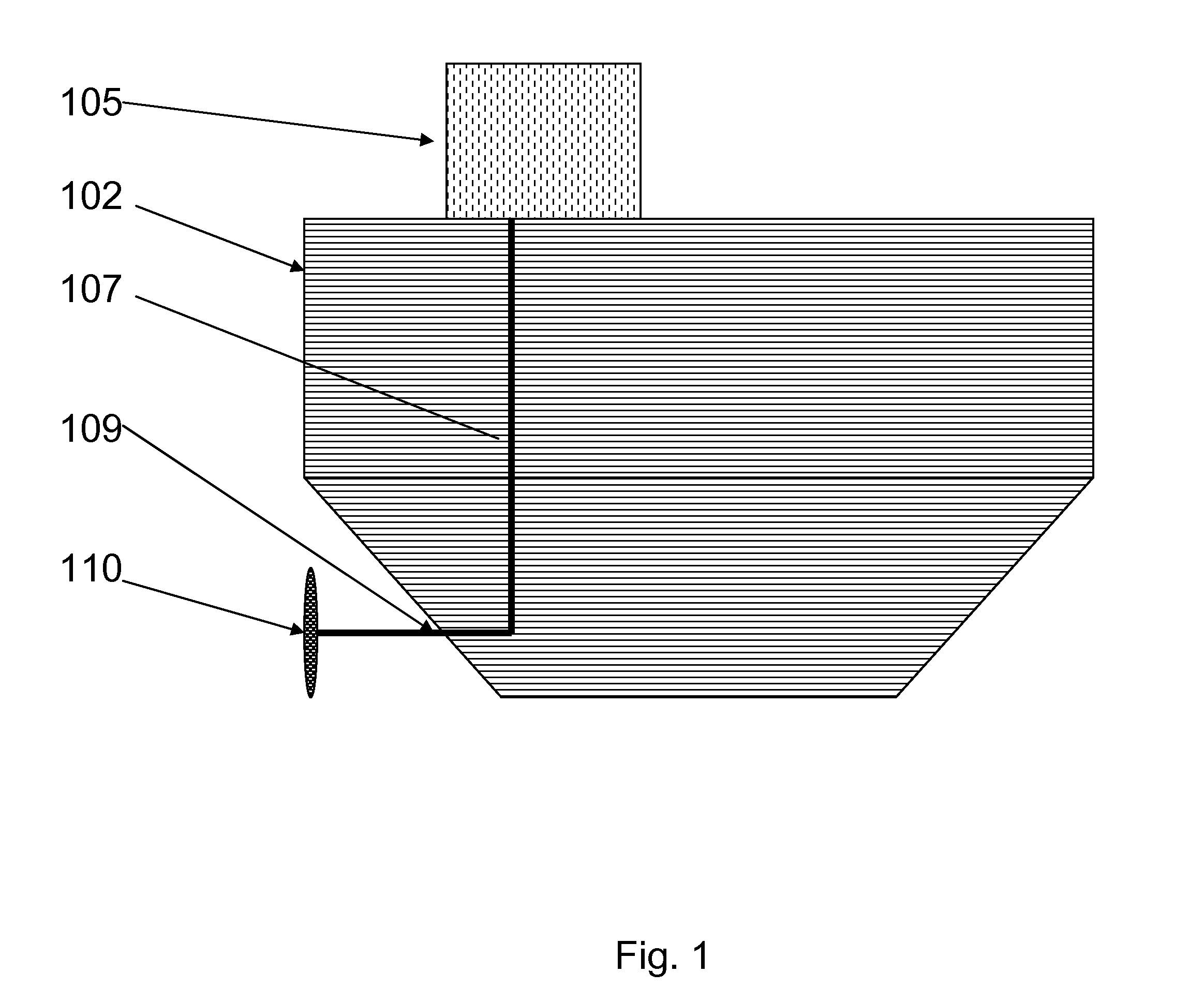
[0051]Attention is now turned to FIG. 2 which shows an alternative embodiment of the present invention. Power plant 205 used in desalination operations is present on vessel 202. Due to the size of the vessel 202, additional energy is required for both propulsion of vessel 202 and desalination. A solar energy system 220 is present on vessel 202 for converting sunlight into electrical energy that may be used for driving a driveshaft 209 of a propeller 210 associated with vessel 202. The solar energy system 220 may be a mirror-based solar-thermal system or may employ any method for converting solar energy into electricity used for driving propeller 210. A computer 240 can determine the balance in use of power plant 205 or solar energy system 220 at any given time for propelling vessel 202. During very sunny days, the solar energy system 220 may be primary, whereas at night, the vessel 202 might rely solely on the power plant 205 for providing power to drive the driveshaft 209 of vessel...
third embodiment
[0052]Attention is turned to FIG. 3A which shows an embodiment of the present invention. Vessel 302 moving through water (303) (arrow indicates direction of vessel 302) includes an electricity-producing power plant 305 of greater than 20 MW rating for driving a propeller 310. It additionally includes a wave energy receiving component 350. The wave energy receiving component 350 can convert wave and / or water flow 355 into electricity through an associated wave energy to electrical energy conversion element 360. A computer 340 can determine the balance of power supplied to driveshaft 309 and thus propeller 310 from power plant 305 and conversion element 360. The computer can continuously balance energy being delivered from the power plant 305 and the conversion element 360 to driveshaft 309 so as to allow for the most efficient use of energy resources. Quiet seas may require more power plant 305 power based on converting natural gas or the like to electricity while stormy seas may yie...
PUM
 Abstract
Description
Claims
Application Information