Die Cast Rotor With Steel End Rings to Contain Aluminum

a technology of aluminum end rings and die cast rotors, which is applied in the direction of magnetic circuit rotating parts, synchronous motors, magnetic circuit shapes/forms/construction, etc., can solve the problems of rotor bars not experiencing the same amount of radial growth, fatigue stress, failure of the machine, etc., and achieve the effect of reducing hoop stress

Active Publication Date: 2011-11-24
BAE SYSTEMS CONTROLS INC
View PDF2 Cites 4 Cited by
  • Summary
  • Abstract
  • Description
  • Claims
  • Application Information

AI Technical Summary

Benefits of technology

[0005]An end ring that is continuous for a full 360 degrees experiences radial growth due to both thermal expansion and rotational speed related growth. Both of these feed into the hoop stress of the end ring and more importantly into the fatigue stress of the end ring to rotor bar interface. An electric machine consists of many rotor bars that are enclosed by the steel laminations; these bars extend thru the laminations and connect to the machine end rings on each side the rotor. These end rings expand in the radial direction as mentioned above. However, the rotor bars do not experience the same amount of radial growth as the end rings because they are enclosed by the steel laminations. The result is an end ring that expands and contracts in the radial direction at a much higher rate than the rotor bars causing a fatigue stress at the joint of the end ring to rotor bar interface. The fatigue stress at this joint will introduce a crack and over time ultimately fail the machine. This disclosure helps the rotor in two distinct ways. First, by breaking the end ring into sections it limits the thermal growth to each section thus reducing the thermal growth of the entire the ring. Second, the geometry of the spoked end ring helps contain the end ring at high speed by acting like a band as used in rotors today. These improvements reduce the amount of radial growth of the end ring and reduce the fatigue stress at the joint location and hoop stress in the end rings. A minimum of two end rings are required per side of the rotor, this is due to the fact that the end ring still needs to connect all of the rotor bars together for the machine to work. By rotating the first end ring relative to the second end ring the resulting cast material will connect all the rotor bars while still providing the benefit of reduced stresses.
[0008]In yet another aspect of the present disclosure, there is provided an end ring for an induction die cast rotor. The end ring has a first member that includes a first ring connected to a first hub by a plurality of first spokes. The end ring also has a second member connected to the first member. The second member includes a second ring connected to a second hub by a plurality of second spokes. The first spokes are offset from the second spokes by a predetermined amount. The first and second spokes form pockets. A different material relative to the first member and the second member extends into the pockets. The first member and the second member reduce a hoop stress caused by thermal fatigue of the rotor that is attributed to the material during cyclic operation of the rotor.

Problems solved by technology

However, the rotor bars do not experience the same amount of radial growth as the end rings because they are enclosed by the steel laminations.
The result is an end ring that expands and contracts in the radial direction at a much higher rate than the rotor bars causing a fatigue stress at the joint of the end ring to rotor bar interface.
The fatigue stress at this joint will introduce a crack and over time ultimately fail the machine.
First, by breaking the end ring into sections it limits the thermal growth to each section thus reducing the thermal growth of the entire the ring.

Method used


Image

  • Die Cast Rotor With Steel End Rings to Contain Aluminum
  • Die Cast Rotor With Steel End Rings to Contain Aluminum
  • Die Cast Rotor With Steel End Rings to Contain Aluminum

Examples


Embodiment Construction

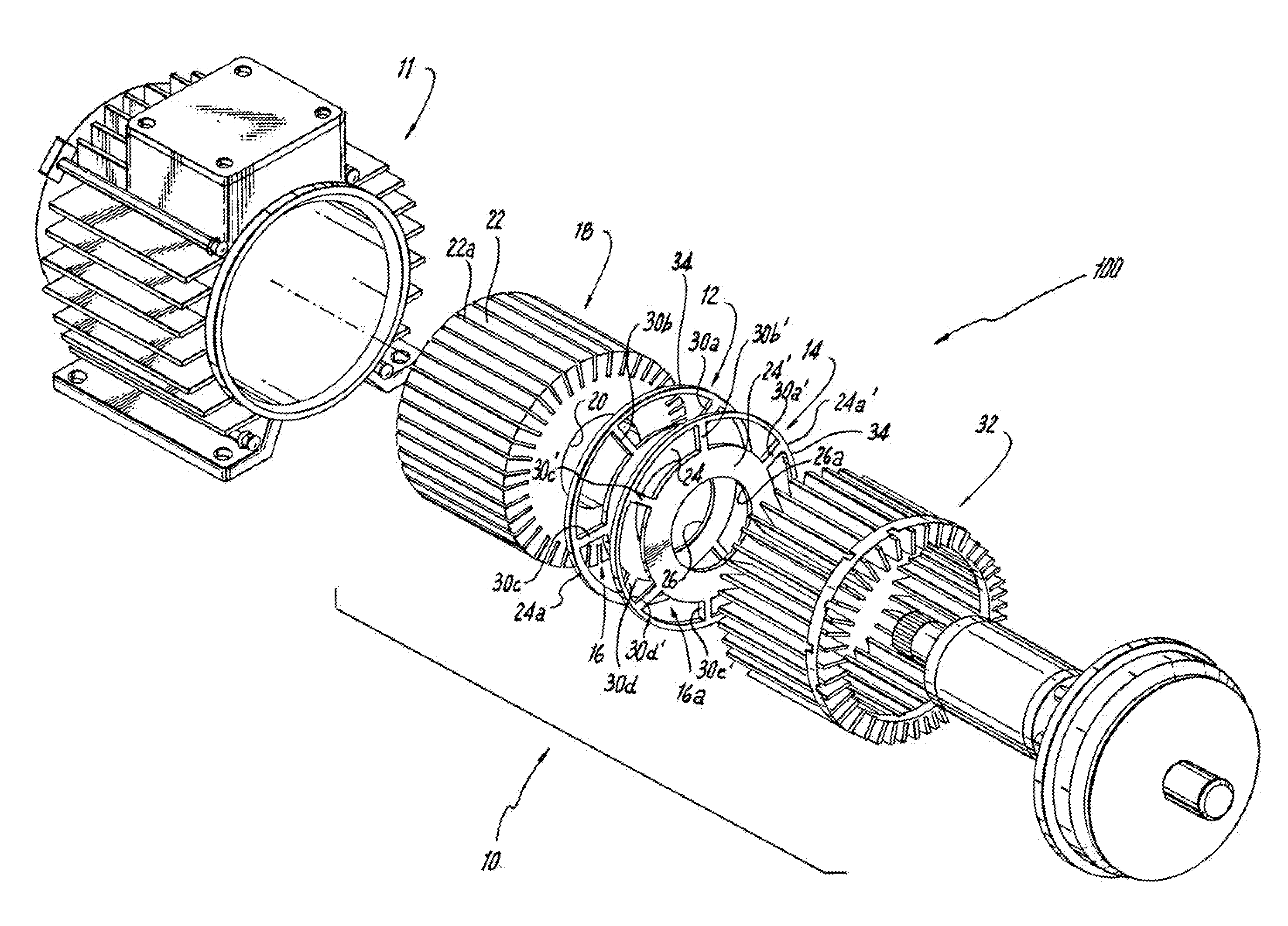
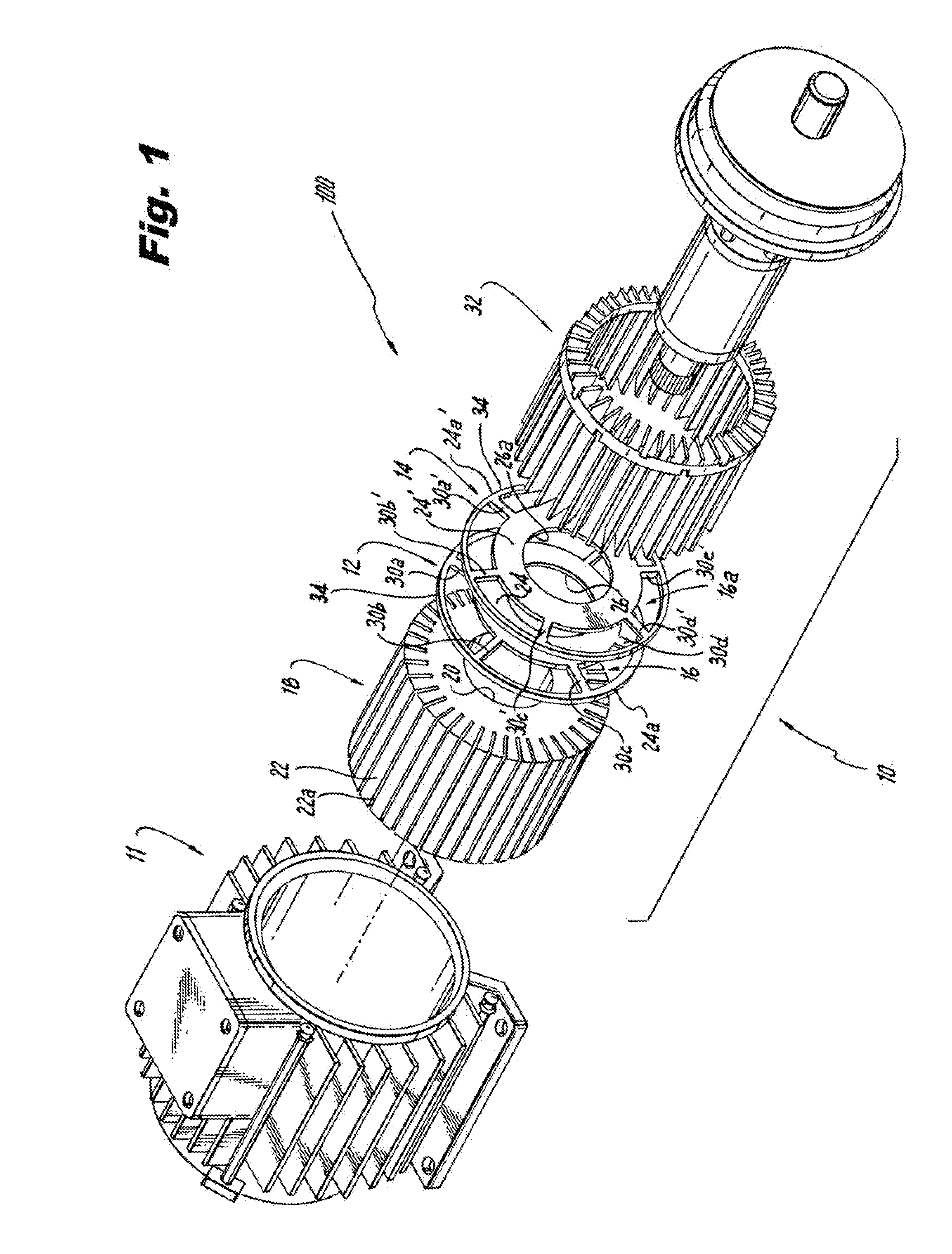
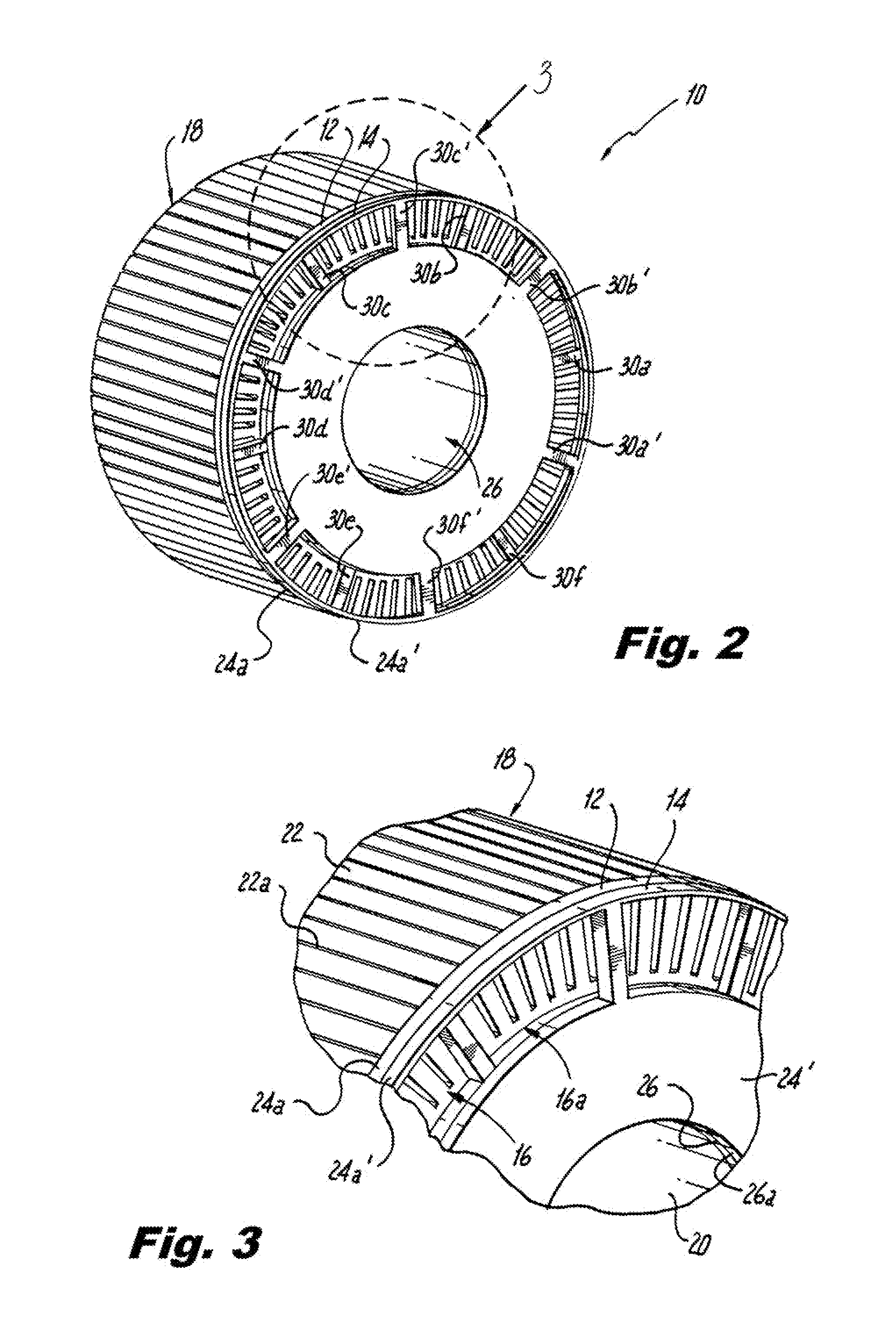
[0017]The present disclosure is directed to an electric machine 100 such as an induction motor or generator having a rotor 10 and a stator 11. In the illustrated embodiment, the rotor 10 is advantageously cast from pure aluminum, which encompasses a first and a second end ring 12, 14 made preferably from steel or a steel alloy. It should be appreciated that the present disclosure is not limited to these specific materials, and other suitable materials can be used to form the rotor 10. The steel end rings 12, 14 preferably are adapted to contain the aluminum at high speeds of rotation by breaking up the end rings 12, 14 into one or more pockets 16, 16a to reduce hoop stresses caused by thermal fatigue. It should be appreciated that casting with pure aluminum using the steel end rings 12, 14 preferably provides several benefits. First, suitable mechanical strength is provided by the end rings 12, 14, while the aluminum provides suitable casting, thermal, and electrical properties. Thi...


PUM

PropertyMeasurementUnit
diameteraaaaaaaaaa
thickaaaaaaaaaa
thickaaaaaaaaaa

Abstract

A rotor for an electrical inductor motor or an induction generator includes a core having spaces formed in the core. The rotor also has a first end ring. The first end ring has a first hub portion. A first ring is connected to the first hub portion by first spokes. The rotor also has a second end ring. The second end ring has a second hub portion. A second ring is connected to the second hub portion by second spokes. The first end ring is secured to the core. The second end ring is rotated a predetermined amount so the first spokes are misaligned with the second spokes. The second end ring is connected to the first end ring and the core. The core, the first end ring and the second end ring form a substrate. An aluminum conductor is cast to the substrate. The aluminum conductor fills in the spaces and around the first and second spokes to form a cast rotor.

Description

RELATED APPLICATION[0001]This application is a divisional of U.S. Ser. No. 12 / 349,615, filed Jan. 7, 2009, the entire contents of which are incorporated herein by reference.FIELD OF THE INVENTION[0002]The present disclosure relates to a rotor for an induction generator or motor. More particularly, the present disclosure relates to a rotor that includes resilient end rings that permit a new method for the rotor to be die cast with an aluminum material.DESCRIPTION OF THE RELATED ART[0003]Electric rotors for motors and generators can rotate relative to a stator generally at speeds of up to 10,000 to 15,000 rpm. Generally, a retention mechanism is needed to keep the end ring connected to the body of the rotor. Sometimes, a band of a high strength material can be secured to each end ring of the rotor to secure it to the body. Rivets can also be cast into the rotor to secure the end rings to the body. Additionally, some solutions use special laminations to secure the body with the end rin...

Claims


Application Information

Patent Timeline
Patent Type & Authority Applications(United States)
IPC IPC(8): H02K15/02
CPCH02K1/22Y10T29/49012Y10T29/49009H02K1/26H02K15/0012
Inventor CZEBINIAK, DAVID JOSEPH
Owner BAE SYSTEMS CONTROLS INC
Why Eureka
Try Eureka