

Antenna Structure of a Radio Frequency Identification System Transponder
- Summary
- Abstract
- Description
- Claims
- Application Information
AI Technical Summary
Benefits of technology
Problems solved by technology
Method used
Image

Examples
first embodiment
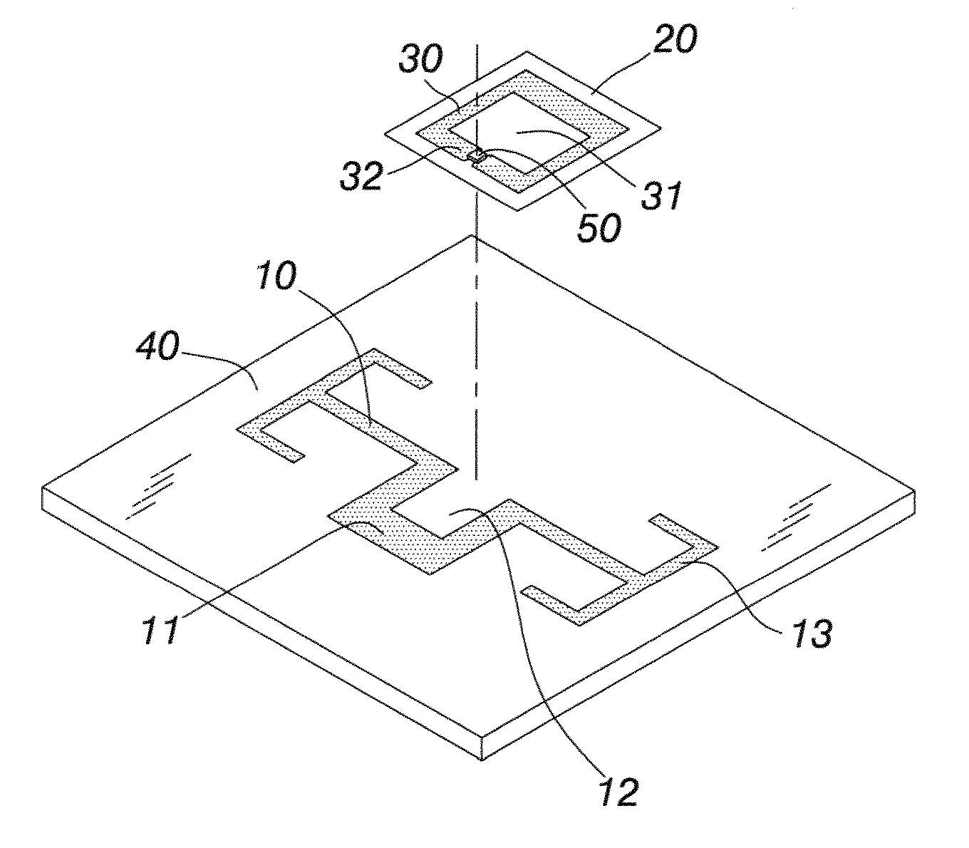
Referring to FIG. 3 and FIG. 4, an antenna structure of an RFID transponder of the present invention comprises an antenna body 10 which is provided with a coupling part 11. A foldback circuit 30 which includes an insulation layer 20 is provided on the antenna body 10, the coupling part 11 is in a winding shape and is provided with a gap 12; whereas, the antenna body 10 is extended outward from two sides of the coupling part 11 to form antenna parts 13. Upon implementation, the antenna body 10 that includes the coupling part 11 and the antenna parts 13 can be provided on a non-conductive antenna substrate 40, and according to design, the antenna parts 13 can have various shapes, such as a dipole antenna, not limited by the shape of the antenna parts 13 in the drawings.
The aforementioned foldback circuit 30 is in the winding shape, and the gap 12 corresponding to the coupling part 11 is provided with an opening 31 which faces toward the coupling part 11, wherein, the opening 31 of the...
second embodiment
As the present invention utilizes the electromagnetic induction to transmit the signals, when the antenna body 10 and the foldback circuit 30, RFIC 50 are implemented, the coupling part 11 of the antenna body 10 can be provided with the insulation layer 20 and the foldback circuit 30, as shown in a schematic view of a structure of the present invention in FIG. 8; wherein, the coupling part 11 is in the winding shape and is provided with the gap 12, whereas the antenna body 10 is extended outward from two sides of the coupling part 11 to form the antenna parts 13.
The antenna body 10 is provided at a rear side of the non-conductive antenna substrate 40. The foldback circuit 30 is provided with the opening 31, and is extended inward from two sides of the opening 31 to approach conductive parts 32. In addition, the RFIC 50 is provided at the opening 31 or between the conductive parts 32 at two sides. The foldback circuit 30 and the RFIC 50 are provided on the insulation layer 20 and are...
third embodiment
Referring to FIG. 9, it shows a schematic view of a structure of the present invention. The antenna body 10 is provided at the rear side of the non-conductive antenna substrate 40, whereas the foldback circuit 30 and the RFIC 50 are directly provided on a front side of the antenna substrate 40, at positions corresponding to the coupling part 11, allowing the non-conductive antenna substrate 40 to form the insulation layer between the antenna body 10 and the RFIC 50 of the foldback circuit 30.
PUM
 Abstract
Description
Claims
Application Information