Open end variable bleed solenoid (VBS) valve with inherent viscous dampening

Inactive Publication Date: 2011-11-24
BORGWARNER INC
View PDF9 Cites 36 Cited by
  • Summary
  • Abstract
  • Description
  • Claims
  • Application Information

AI Technical Summary

Benefits of technology

[0009]In another aspect of the embodiments of the present invention, a pressure control valve is provided including a housing, a control port at a first end of the housing, and an exhaust port and an associated poppet valve seat at a second end of the housing. A valve shaft is mounted within the housing and includes a first end, a second end, a shaft passage extending therethrough, and a poppet located at the shaft second end. The poppet is operably associated with the valve seat and the exhaust port. The shaft first end has a first diameter and the shaft second end has a second diameter larger than the first diameter. An exterior of the shaft defines an area usable for controlling control volume pressure. This control area is defined by a diff

Problems solved by technology

When the valve is used in such an application, there are many potential sources of hydraulic and/or electro-mechanical “noise” in the fluid system which can initiate or aggravate system instability by, for example, causing sympathetic harmonic vibrations in related system components.
When a pressure control solenoid responds to electronic and/or hydraulic system noise by being forced into an uncontrolled vibration response, the system providing fluid to vehicle components may beco

Method used


Image

  • Open end variable bleed solenoid (VBS) valve with inherent viscous dampening
  • Open end variable bleed solenoid (VBS) valve with inherent viscous dampening
  • Open end variable bleed solenoid (VBS) valve with inherent viscous dampening

Examples


Embodiment Construction

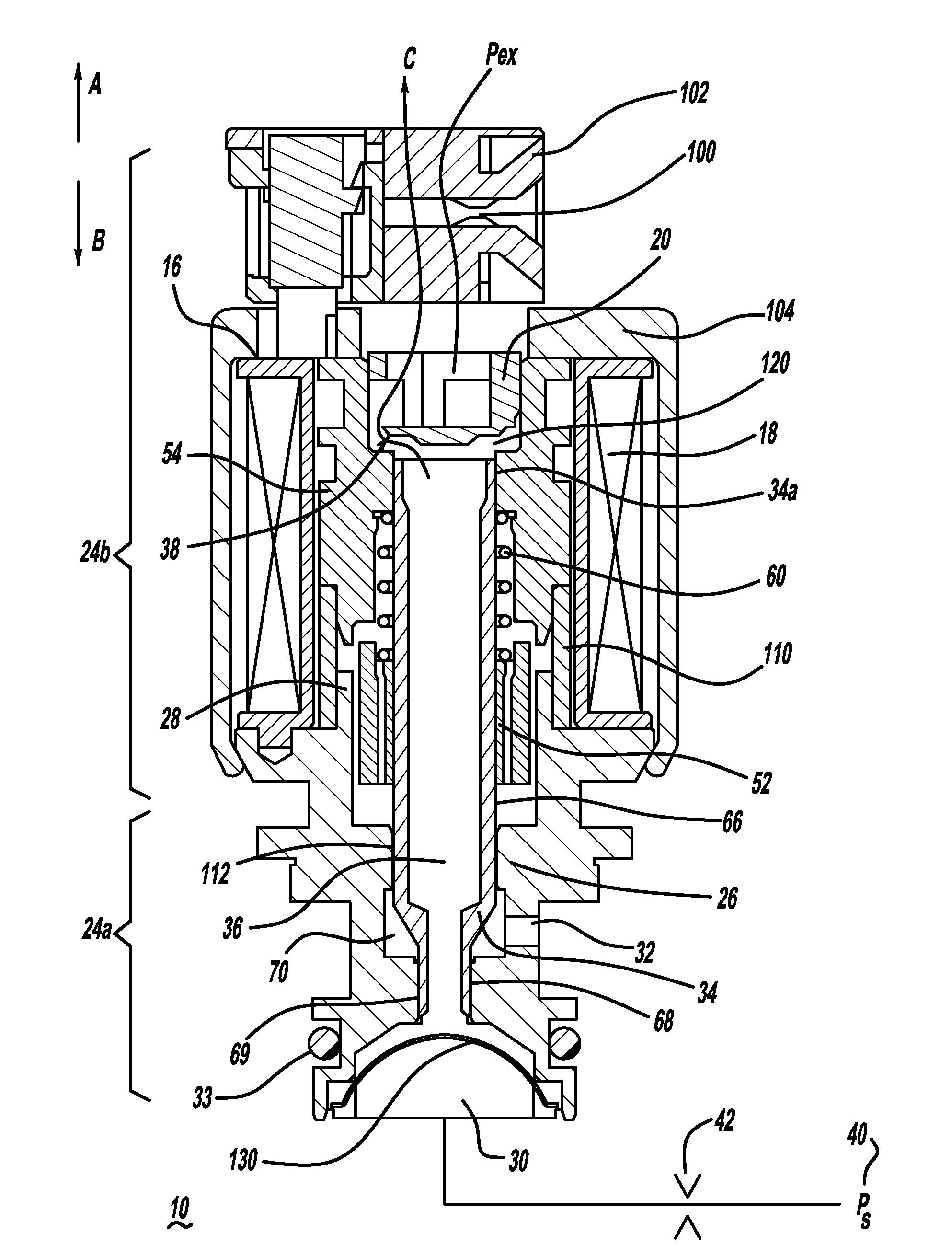
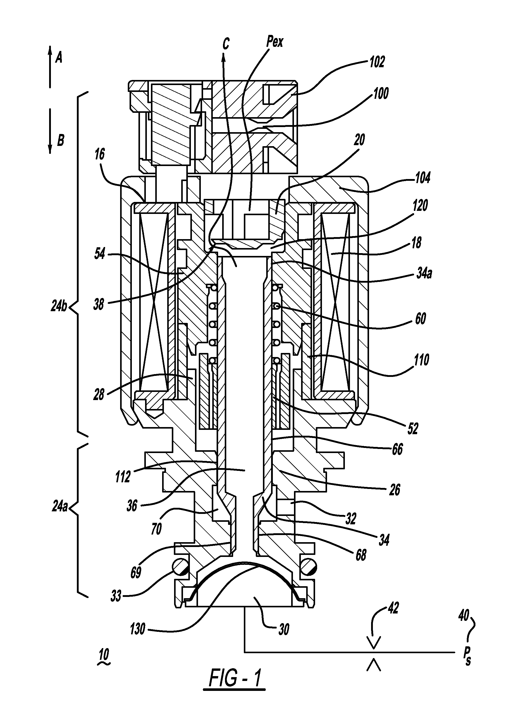
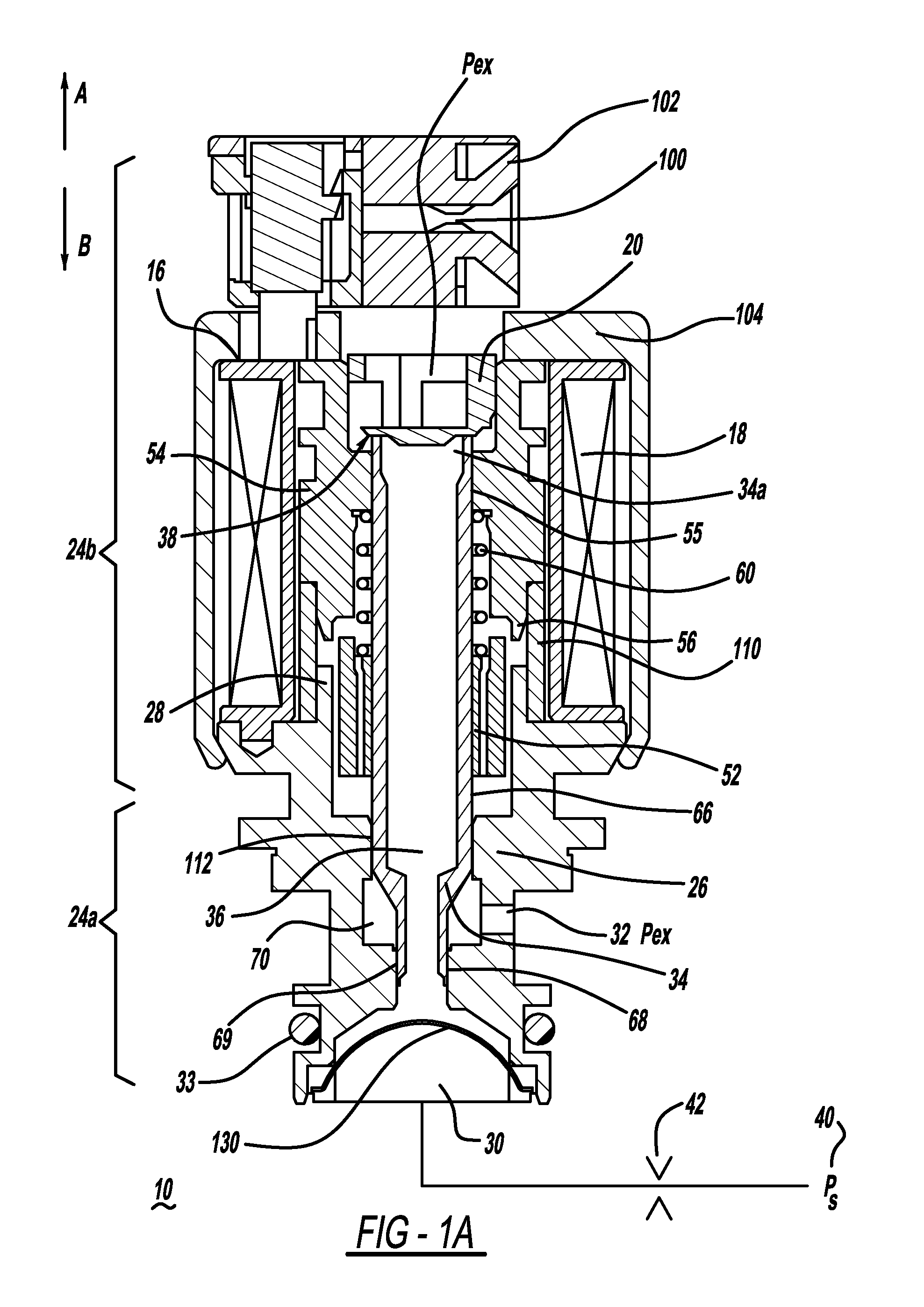
[0014]FIGS. 1 and 1A depict longitudinal cross-sectional views of a normally open, open ended variable bleed solenoid valve 10. The valve 10 has a solenoid portion 24b which includes a housing 104 that encases a bobbin 16 having a coil 18 of wire wound upon the bobbin 16.

[0015]The wire is terminated to connector blades or terminals 100 that are coupled to the bobbin. The bobbin also contains features that allow for a structural connection to a connector shroud 102 that surrounds the connector blades 100 to protect them and isolate them from the remainder of the solenoid, to aid in preventing electrical shorts. A housing 104 formed from steel or another material having a high magnetic permeability surrounds the coil 18 and bobbin 16 and serves to transfer magnetic flux to the other portions of the magnetic circuit when the solenoid valve is energized. When the coil 18 is energized there is a magnetic field generated in the solenoid portion 24b. The solenoid portion 24b also has a val...


PUM


Abstract

A solenoid valve (10) includes a solenoid portion (24b) and a hydraulic portion (24a) having a valve housing (26) connectable to the solenoid portion (24b). A valve shaft (34) mounted in the housing (26) includes a first end positioned in the solenoid portion (24b) and a second end positioned in the hydraulic portion (24a). The valve shaft (34) includes a passage (36) disposed therethrough to allow fluid flow through the valve shaft (34). A valve (38) is located at the first end of the valve shaft (34). When the valve shaft (34) is moved in a first direction, the valve (38) moves toward a closed position, and when the valve shaft (34) is moved in a second direction, the valve (38) moves toward an open position.

Description

FIELD OF THE INVENTION[0001]The present invention relates to solenoid operated hydraulic control valves.BACKGROUND OF THE INVENTION[0002]The use of solenoid operated hydraulic control valves in hydraulic control systems is well-known. One application of such a valve is in an electronically controlled automatic transmission of an automobile. In an automatic transmission, a solenoid pressure control valve usually controls many critical system parameters and performance of the valve should be consistent and stable.[0003]When the valve is used in such an application, there are many potential sources of hydraulic and / or electro-mechanical “noise” in the fluid system which can initiate or aggravate system instability by, for example, causing sympathetic harmonic vibrations in related system components. When a pressure control solenoid responds to electronic and / or hydraulic system noise by being forced into an uncontrolled vibration response, the system providing fluid to vehicle componen...

Claims


Application Information

Patent Timeline
IPC IPC(8): F16K31/02
CPCF16H61/0251H01F7/1607F16K31/0651
Inventor HAYNES, WILLIAM D.ALLBERT, MATTHEW T.
Owner BORGWARNER INC
Why Eureka
Try Eureka