

Light emission module, light emission module manufacturing method, and lamp unit
a technology of light emission module and manufacturing method, which is applied in the direction of vehicle headlamps, transportation and packaging, lighting and heating apparatus, etc., can solve the problems of reducing the light intensity of the light, and affecting the use efficiency of light by the light wavelength conversion member. achieve the effect of improving the light efficiency of the light wavelength conversion member
- Summary
- Abstract
- Description
- Claims
- Application Information
AI Technical Summary
Benefits of technology
Problems solved by technology
Method used
Image

Examples
first embodiment
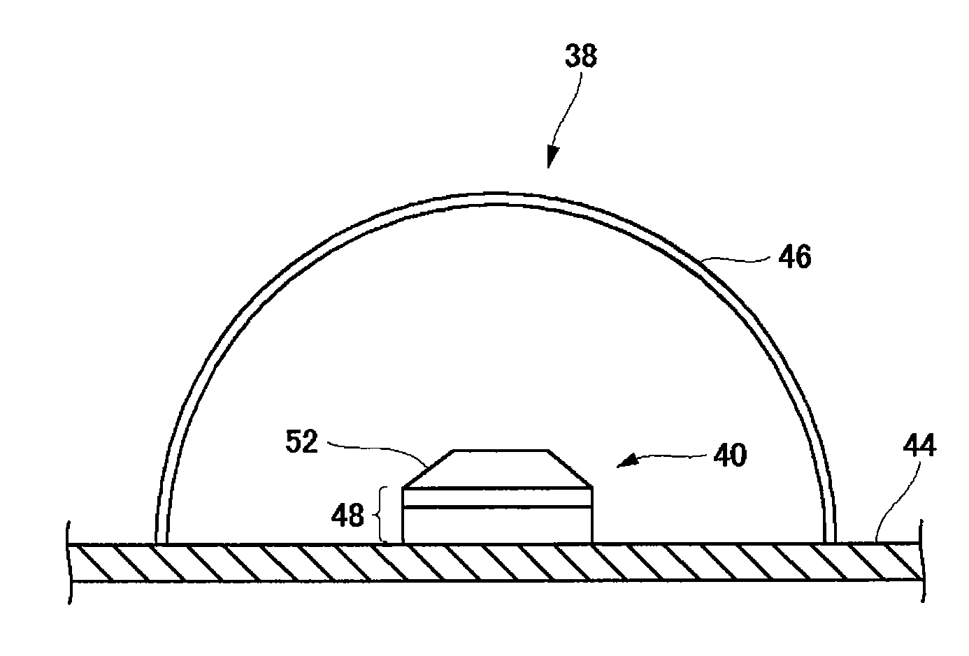
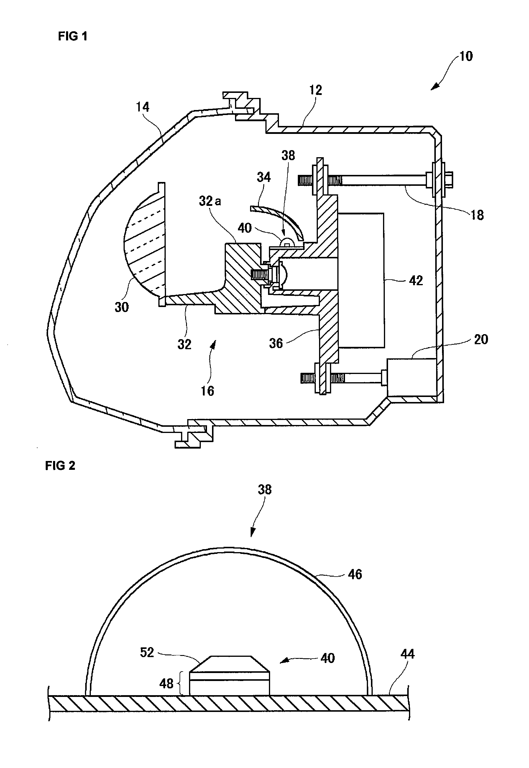
[0062]FIG. 1 is a sectional view illustrating the configuration of an automotive headlamp 10 according to a first embodiment. The automotive headlamp 10 has a lamp body 12, a front cover 14, and a lamp unit 16. Hereinafter, descriptions will be made, assuming that the left side in FIG. 1 is the front of the lamp and the right side therein is the back thereof. In addition, when viewing the front of the lamp, the right side is referred to as the right side of the lamp and the left side as the left side thereof. FIG. 1 illustrates the section of the automotive headlamp 10 cut by the vertical plane including the light axis of the lamp unit 16, when viewed from the left side of the lamp. When the automotive headlamp 10 is to be mounted in a vehicle, the automotive headlamps 10, which are formed symmetrically with each other, are provided in the left and right front portions of the vehicle, respectively. FIG. 1 illustrates the configuration of either of the left and right automotive headl...
second embodiment
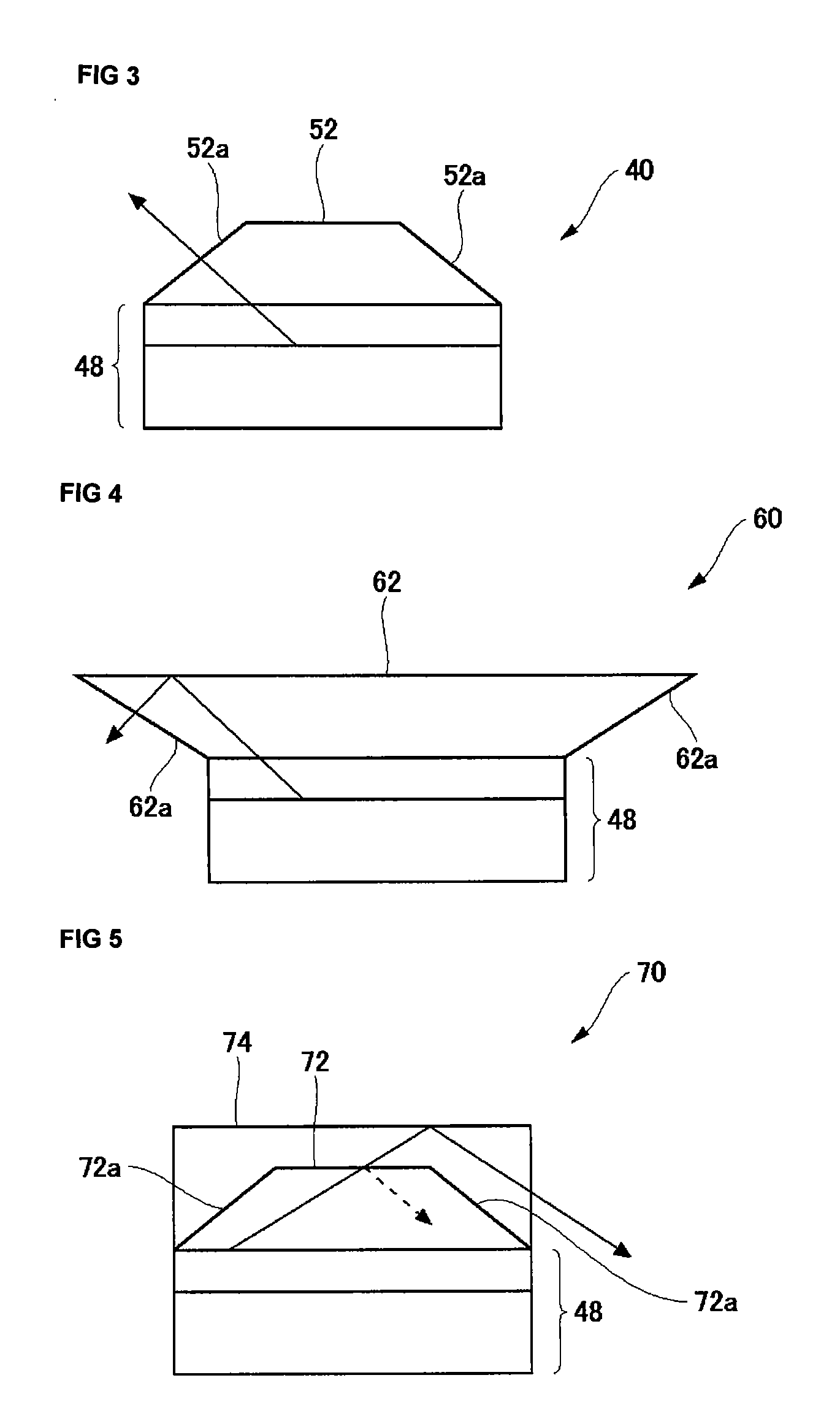
[0079]FIG. 4 is a view illustrating the configuration of a light emitting module 60 according to a second embodiment. The configuration of the automotive headlamp 10 is the same as that in the first embodiment, except that the light emitting module 60 is provided instead of the light emitting module 40. Hereinafter, the parts similar to those in the first embodiment will be denoted with the same reference numerals and descriptions thereof will be omitted.
[0080]The configuration of the light emitting module 60 is the same as that of the aforementioned light emitting module 40, except that light wavelength conversion ceramic 62, which is a light wavelength conversion member, is provided instead of the light wavelength conversion ceramic 52. The light wavelength conversion ceramic 62 has a tapered surface 62a that slopes such that the thickness thereof is reduced toward the end portion thereof. In the second embodiment, the tapered surface 62a slopes so as to protrude in the direction ...
third embodiment
[0082]FIG. 5 is a view illustrating the configuration of a light emitting module 70 according to a third embodiment. The configuration of the automotive headlamp 10 is the same as that in the first embodiment, except that the light emitting module 70 is provided instead of the light emitting module 40. Hereinafter, the parts similar to those in the aforementioned embodiments will be denoted with the same reference numerals and descriptions thereof will be omitted.
[0083]The configuration of the light emitting module 70 is the same as that of the aforementioned light emitting module 40, except that light wavelength conversion ceramic 72, which is a light wavelength conversion member, and transparent ceramic 74 are provided instead of the light wavelength conversion ceramic 52. The light wavelength conversion ceramic 72 is formed into the same shape as that of the light wavelength conversion ceramic 52 in the first embodiment. Accordingly, the light wavelength conversion ceramic 72 als...
PUM
 Abstract
Description
Claims
Application Information