LED Driver for Driving LED Lighting Device at High Frequency

a technology of led lighting and driver, applied in the field of electronic devices, can solve the problems of high-value passive components, high-value passive components, and increased losses of diodes with high frequency, and achieve the effect of low switching loss

Inactive Publication Date: 2011-11-24
LUXERA
View PDF2 Cites 16 Cited by
  • Summary
  • Abstract
  • Description
  • Claims
  • Application Information

AI Technical Summary

Benefits of technology

[0007]According to one aspect of the present invention, a driver device for driving an LED lighting device is provided. The driver device includes at least one power switch adapted to operate at a switching frequency of greater than 500 KHz and adapted to control the driving current provided to the LED lighting device. An LED controller circuit is coupled to the power switch and is operable to control the switching of the power switch. Operating the power switch at such a high frequency allows a substantial reduction in passive devices such as inductors and capacitors.
[0008]In one embodiment, the power switch is made from a material having a band gap of greater than 1.2 eV. This allows the driver device to be operated at a high frequency with low switching loss.

Problems solved by technology

While the PWM principle has been well known for decades, an off line LED driver (driver that receive power from a household power line which ranges from 100 volts to 230 volts rms) application presents a particular challenge due to high switching voltages (e.g., 170V-330V peak-to-peak depending on line voltage and driver topology).
In addition to FET parasitic capacitance, diode reverse recovery losses increase with high frequency as well.
However, using such a low PWM frequency requires high value passive components, such as capacitors and inductors.
High value passive components present a number of drawbacks such as high cost, large size, and high parasitics.
However, electrolytic capacitors are particularly unsuitable for off line retrofit LED lighting because of reduced lifetime at high temperature, which is far shorter than the expected lifetime of 50,000 hours for an LED source.

Method used


Image

  • LED Driver for Driving LED Lighting Device at High Frequency
  • LED Driver for Driving LED Lighting Device at High Frequency
  • LED Driver for Driving LED Lighting Device at High Frequency

Examples


Embodiment Construction

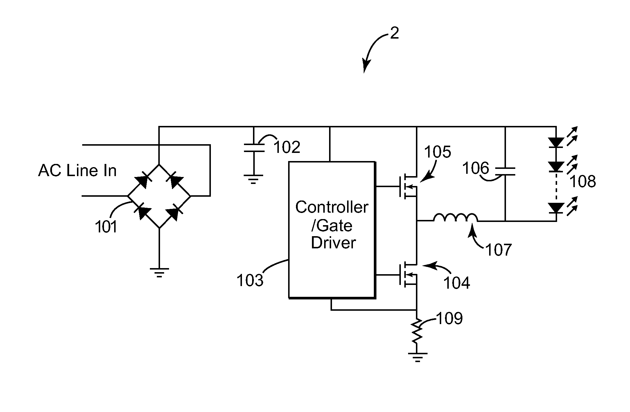
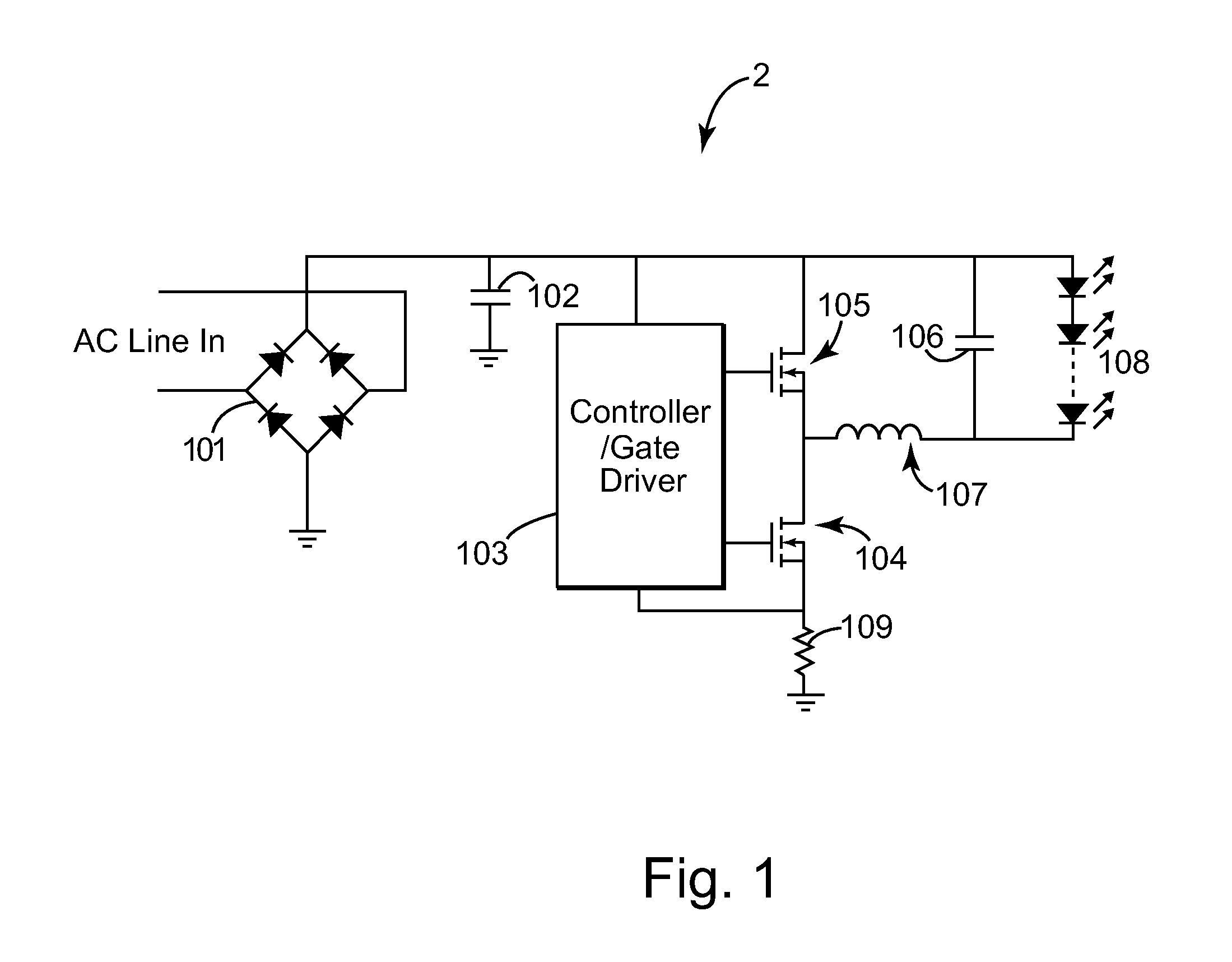
[0013]As used herein, the components of an LED driver can be divided into two distinctive types: i) power devices and ii) control devices. Power devices are defined as electronic devices that are used to deliver power to other devices, components, and modules. Control devices are devices that sense, amplify, and convert signals to monitor and to control the power devices.

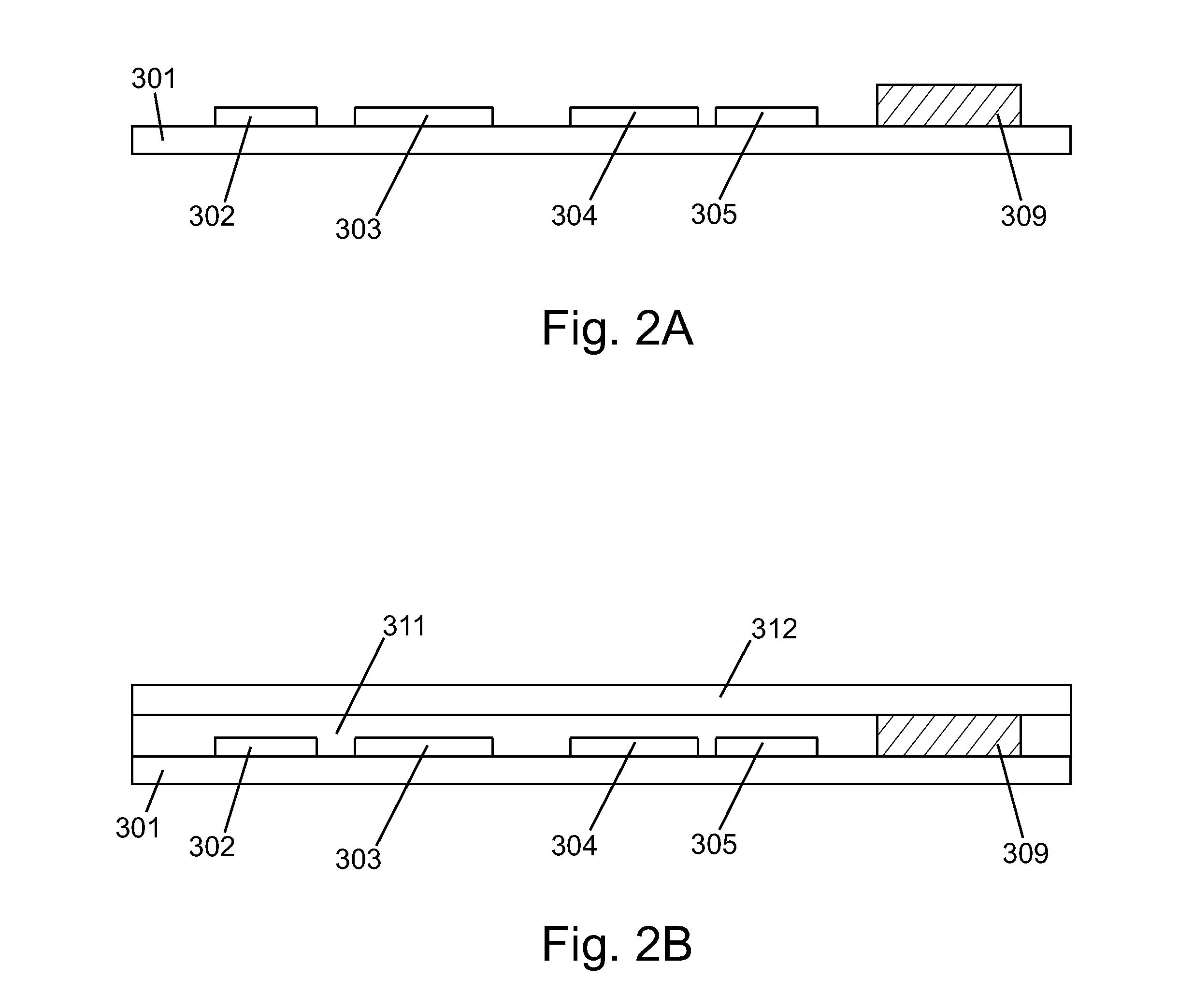
[0014]Briefly, the present invention substantially reduces switching losses and reduces the values and size of passive components, such as capacitors and inductors. The present invention also implements capacitors and inductors as devices that are integrated together on a common substrate, as opposed to discrete components on a PCB. In one embodiment, the present LED driver replaces a PCB with an inorganic substrate with improved matching and higher thermal conductivity. The present invention utilizes parallel processing of multiple components. As a result, as higher level of integration removes cost and space const...


PUM

PropertyMeasurementUnit
band gapaaaaaaaaaa
capacitanceaaaaaaaaaa
inductanceaaaaaaaaaa

Abstract

A driver device for driving an LED lighting device includes at least one power switch adapted to operate at a switching frequency of greater than 500 KHz and adapted to control the driving current provided to the LED lighting device. Operating the power switch at such a high frequency allows a substantial reduction in passive devices such as inductors and capacitors.

Description

CROSS REFERENCE TO RELATED APPLICATIONS[0001]This application claims the benefit of priority under 35 U.S.C. Section 119(e) to U.S. Provisional Application Ser. No. 61 / 345,990, filed May 18, 2010, entitled “Apparatus and Method for Operating a Light Emitting Diode Lighting Device at High Frequency”, which is fully incorporated by reference herein.FIELD OF THE INVENTION[0002]The present invention is related generally to the field of electronic devices. More particularly, the present invention is related to the field of electronics for light emitting diode lighting applications.BACKGROUND OF THE INVENTION[0003]An operating Light Emitting Diode (LED) lighting device requires an energy efficient and cost effective electronic driver circuit. Currently, the most common solution is to apply pulse width modulation (PWM) to LED lighting devices to generate constant forward current and to control brightness by adjusting PWM duty cycle with a number of available options such as, among others, ...

Claims


Application Information

Patent Timeline
Patent Type & Authority Applications(United States)
IPC IPC(8): H05B37/02
CPCH05B33/0815Y10T29/49071H01L2224/04105H01L2224/24137H01L2224/2518H01L2224/92144H01L2924/19042H01L2924/19105H05B45/3725H05B45/375H05B45/38H05B45/385
Inventor CHOUTOV, DMITRI A.LIVSCHITZ, LEONARD S.
Owner LUXERA
Why Eureka
Try Eureka