Cooling air cleaner of an electronic device

Active Publication Date: 2011-11-24
NOVOMATIC
View PDF22 Cites 19 Cited by
  • Summary
  • Abstract
  • Description
  • Claims
  • Application Information

AI Technical Summary

Benefits of technology

[0004]Accordingly, the object of the present invention is to create an improved air cleaner of the above

Problems solved by technology

A reduced air permeability of the filter module is particularly critical in cases wherein the air flow to be cleaned is the cool air flow of an electronic device since reduced cooling air flow leads to an increased thermal strain of the electronic components of the electronic d

Method used


Image

  • Cooling air cleaner of an electronic device
  • Cooling air cleaner of an electronic device
  • Cooling air cleaner of an electronic device

Examples


Embodiment Construction

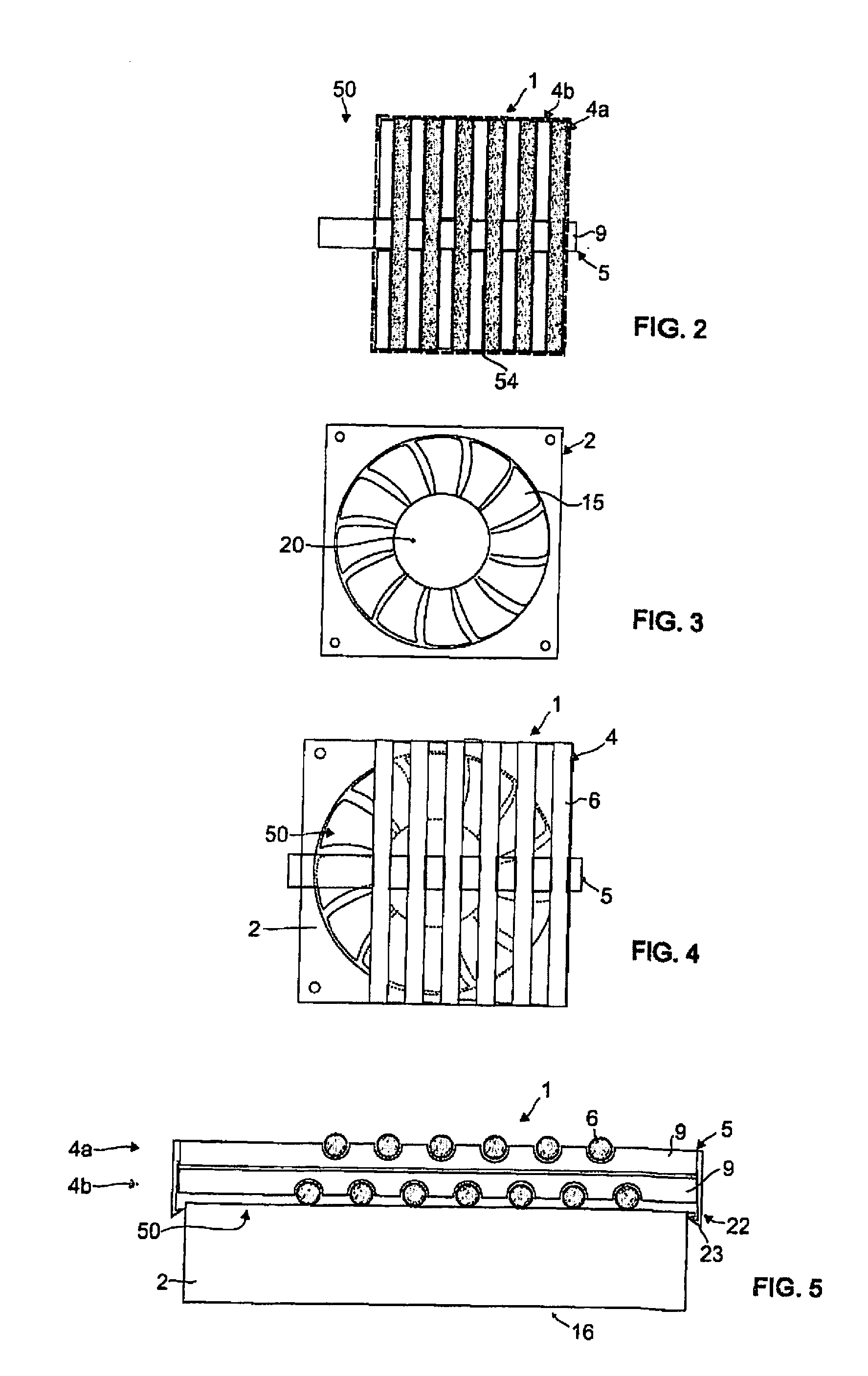
[0058]In the embodiment shown in FIGS. 2 to 6, the air cleaner comprises a filter module 1 as well as a ventilator 2. Ventilator 2 generates an air flow which is cleaned by the mentioned filter module 1. Advantageously, said air cleaner will be installed on the inside of an enclosure (not shown in details here) of an electronic device such as a gambling machine wherein the mentioned air flow serves for cooling the electronic components of the mentioned machine.

[0059]It may be mentioned that the air cleaner may also be used in a computer (PC) with a big, midi or mini tower enclosure or a desktop enclosure or a server station, an industrial PC, in switchboxes or distributor boxes.

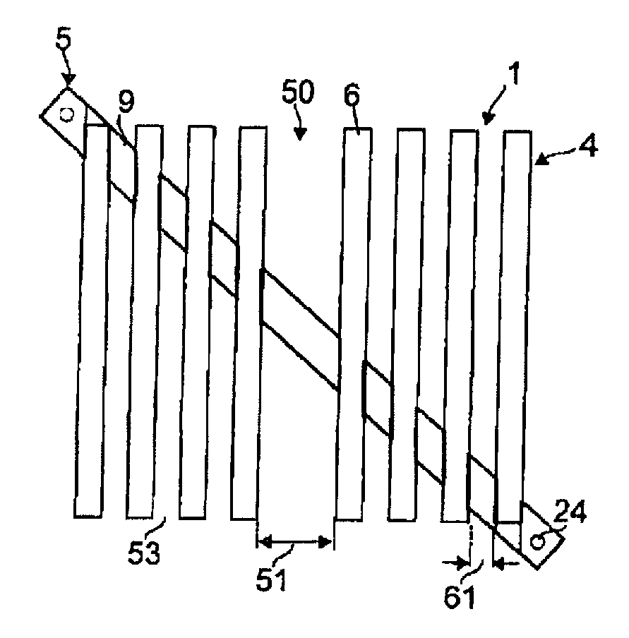
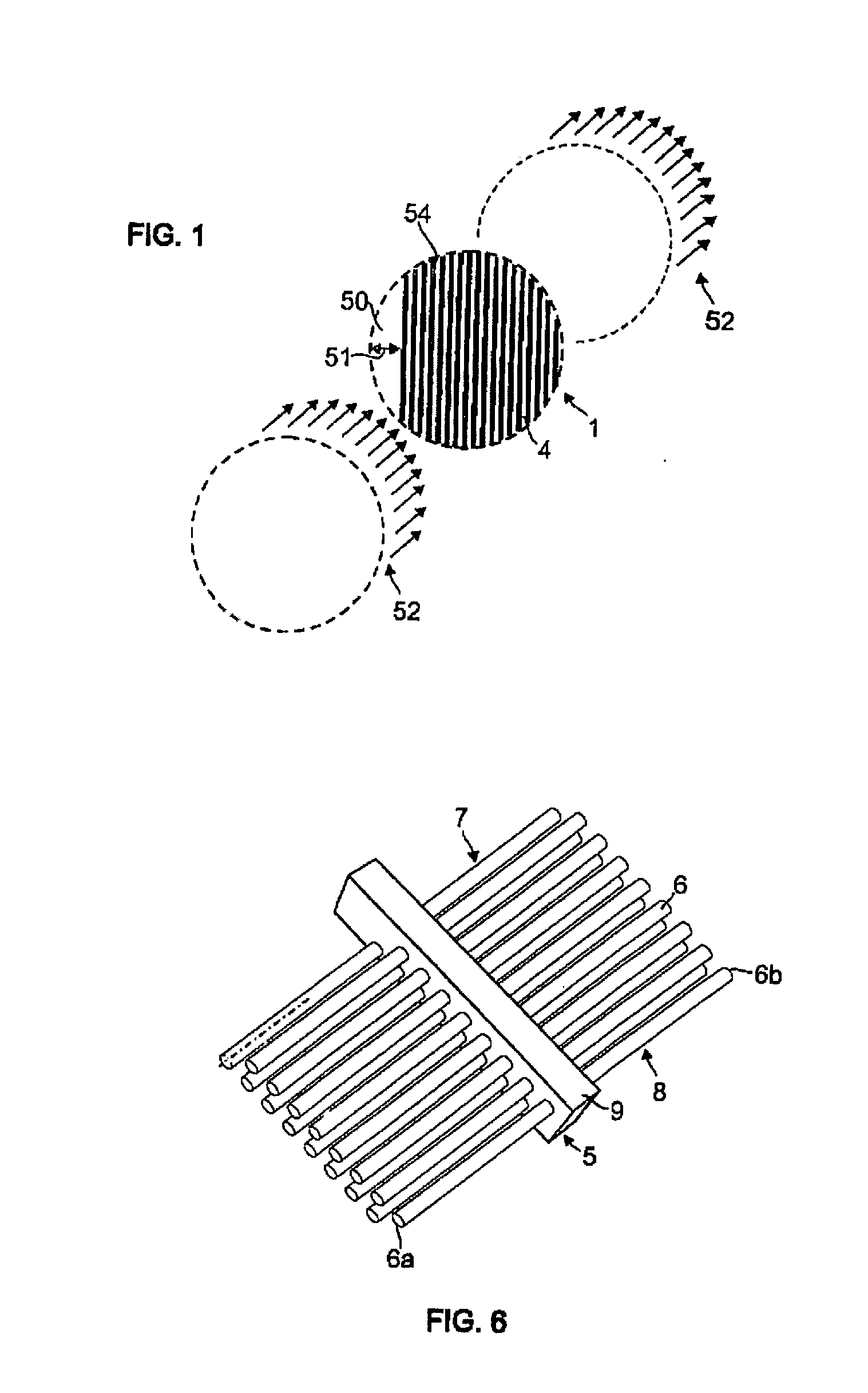
[0060]As shown in FIG. 2, the filter module 1 may consist of elongated, bar shaped filter element 6 (in the drawn version), which—see FIG. 5—are arranged consecutively in two spheres so that the filter module 1 has two (2) filter layers 4 which are located transversely alongside the mentioned air flow 52. Eac...


PUM

PropertyMeasurementUnit
Fractionaaaaaaaaaa
Fractionaaaaaaaaaa
Fractionaaaaaaaaaa

Abstract

The present invention relates to an air cleaner for the removal of pollutants from an air flow by a filter module, the filter module of which comprises at least one permeable filter layer for the accumulation of pollutants on the filter layer. According to the invention, a bypass channel will be provided and established such that part of the unfiltered air flow may bypass any filter layer. Surprisingly, such a bypass channel does hardly compromise the cleaning effect of the filter module, at least as long as the filter layer has not yet been clogged with pollutants since in this case the biggest part of the air flow will take the major path through the filter layer due to lack of resistance. Only if the filter layer is clogged and if resistance for the air flow increases, air will obviously flow through the mentioned bypass channel.

Description

BACKGROUND OF THE INVENTION[0001]The present invention relates to an air cleaner for the removal of pollutants from an air flow with a filter module, the filter module of which comprises at least one permeable filter layer for the accumulation of pollutants on the filter layer.[0002]WO 2007 / 028176 A1 describes an air cleaner for cleaning machine exhaust air, the air cleaner of which has a filter module to remove non-air ingredients. Said filter module comprises several filter layers arranged one after another in the air flow to be cleaned. Each of these layers consists of several filter bars which are parallel but distant from each other wherein the mentioned filter bars are alternatingly set in the successively arranged filter layers in transverse position to the flow direction so that the air flow can take a serpentine-shaped way through the filter module. Said filter bars thereby consist of a porous material such as plastic foam, which is dampened by a fluid such as silicone oil ...

Claims


Application Information

Patent Timeline
IPC IPC(8): H05K5/00B01D46/46B01D46/42
CPCB01D46/0028B01D46/0035B01D46/0087B01D46/0019B01D2273/30B01D2279/45B01D2273/10B01D46/56
Inventor WINKLER, HEINZ
Owner NOVOMATIC
Why Eureka
Try Eureka