
Ct perfusion phantom

a computed tomography and phantom technology, applied in the field of improving therapy and drug tailoring in oncology patients, can solve the problems of limited number of equipment, long and uncomfortable examination time, and large scale us

Inactive Publication Date: 2011-11-24
HADASIT MEDICAL RES SERVICES & DEVMENT
View PDF6 Cites 5 Cited by
  • Summary
  • Abstract
  • Description
  • Claims
  • Application Information

AI Technical Summary

Benefits of technology

[0011]One aspect of the present invention is directed to an apparatus useful for computed tomography imaging, comprising a phantom control reference, comprising a plurality of compartments, each compartment containing contrast material, the contrast material differing in density from one compartment to another throughout the plurality of compartments, the densities of the contrast material in the plurality of compartments forming a series of densities that corresponds to a density curve of blood perfusion of a healthy tissue; and a controller for positioning the compartments in a screening field of view of a CT machine so the CT machine can take a series of images of the compartments at a same examination time that the CT machine takes a series of CT images of the healthy tissue.
[0014]A still further aspect of the present invention is directed to a method of controlling for variability in measurements of healthy tissue blood perfusion for computed tomography imaging, comprising using a particular piece of computed tomography equipment, measuring at a first time a blood perfusion of contrast material in a healthy aorta in a patient while measuring a blood perfusion of the contrast material in a healthy tissue phantom having a known density curve selected to correspond to the blood perfusion of the healthy aorta to obtain a first phantom perfusion result; repeating the measurements at a later time for the patient using a second piece of computed tomography equipment; and normalizing the results of the measurement of the blood perfusion in the healthy tissue found using the second piece of computed tomography equipment by using a change, if any, between the first phantom perfusion result and the second phantom perfusion result.

Problems solved by technology

MRIs and PET / CT are the most sensitive in detection but have drawbacks regarding their large scale use for the millions affected.
These drawbacks include (i) a limited number of equipment (ii) long and uncomfortable examination time and (iii) very expensive to use.
The blood perfusion measured by CT scanners has severe reliability problems.
However, the variables obtained with either technique may be influenced by external and internal factors not reflecting changes in the true tissue perfusion rate.
Since the second CT examination may be performed by a different machine, the results will be unreliable.
One way that the prior art CT examinations have attempted to deal with the variability that distorts the results of CT examinations and limits their reliability and usefulness in drug tailoring is by using a control tissue, such as a healthy aorta, that represents the input function of blood.
In practice, however, this underlying assumption is incorrect.
Accordingly, conventional CT imaging is left with the unreliability caused by the variability associated with the above internal and external factors.
This limits the usefulness of CT examinations in drug tailoring and harms patient outcomes.

Method used


Image

  • Ct perfusion phantom
  • Ct perfusion phantom
  • Ct perfusion phantom

Examples


example 1

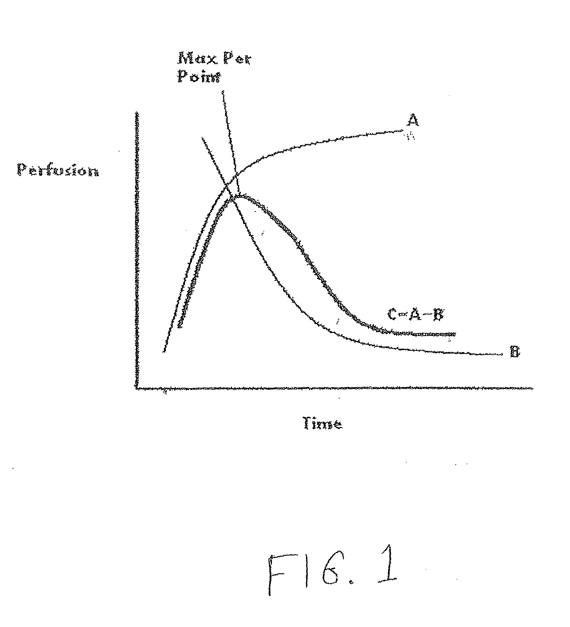
[0053]A patient may be injected with a solution containing a contrast material, for example iodine, at time A for a CT examination and the flow of the contrast material through the cancerous tissue and through the healthy aorta (control tissue) of the patient is observed and imaged by a particular piece of CT equipment during the CT examination. The patient's blood perfusion as measured by the particular piece of CT equipment and is found to be X / 5, where “X” represents the slope (rate of increase from baseline to MaxP or peak enhancement) of the cancerous tissue and the denominator represents the slope of the healthy tissue (i.e. aorta) of the patient. It is noted that in this example the patient's aorta does not receive the drug treatment that the patient's cancerous tissue is receiving.

[0054]The patient is asked to come back for a follow-up CT examination at time B, which in one non-limiting example might be an examination time approximately one day, one week or one month (or any...

example 2

[0058]After injection of contrast material in a liquid solution, the patient's blood perfusion in cancerous tissue and in healthy tissue as measured by the particular piece of CT equipment and is found to be X / 6 at time A. The same patient was re-measured at a follow-up CT examination at time B. The patient's healthy tissue blood perfusion measurement at time B was found to be X / 3, which represents a decline of 50% in blood perfusion of the healthy tissue between time A and time B. This means the healthy tissue was found to be (six) 6 at time A and found to be (three) 3 at time B. When the patient in example 2 was undergoing the CT examination at time A (and similarly when the patient was being examined at time B), a healthy tissue phantom in accordance with one of the embodiments of the present invention was simultaneously being examined by the same CT machine examining the patient. The blood perfusion results of this healthy tissue phantom may have been obtained at time A and at t...

example 3

[0061]Note that in Examples 1 and 2 the observed change in the healthy tissue phantom control reference was less than the observed change in the healthy tissue, which is what may be typical. It could happen, on the other hand, that the measured change in the healthy tissue phantom may be more than the measured change in the aorta because of a change in cardiac output in the other direction Suppose, for example, measurement of the cancerous tissue and of the healthy tissue in the patient at time A was X / 6 and at time B it was X / 5.4, a decline of 10% in perfusion for the healthy tissue (e.g. aorta). When the patient in the above example was undergoing the CT examination at time A (and similarly when the patient was being examined at time B), a healthy tissue phantom in accordance with one of the embodiments of the present invention was simultaneously being examined by the same CT machine examining the patient. Suppose the healthy tissue phantom at time A was 5 (five) and at time B it ...


PUM


Abstract

A physical phantom reference to control for variability of computed tomography measurement results duplicates the density curve of blood perfusion of contrast material in a healthy aorta or large artery to normalize observed changes in healthy arterial blood perfusion when calculating the reduction in tumor blood perfusion between two examination times. In one embodiment, a plurality of compartments with different concentrations of contrast material corresponding to a density curve of blood perfusion of a healthy tissue are positioned-in a screening field of a CT machine so the CT machine images the compartments when it images the healthy tissue. In another embodiment, a pipe containing fluid receives an injection of contrast material from the injector when the injector injects the contrast material into the patient, the pipe having sections of varying diameter so the sections together correspond to a blood perfusion curve of the contrast material in a healthy tissue.

Description

PRIORITY INFORMATION [0001]This patent application claims the benefit of and is a continuation-in-part of U.S. Provisional Patent Application No. 61 / 149,371 filed Feb. 3, 2009.FIELD AND BACKGROUND OF THE INVENTION[0002]The present invention relates to improving therapy and drug tailoring in oncology patients, and, more particularly to improving the reliability of computed tomography (“CT”) examinations measuring the effectiveness of the drug treatment in reducing cancerous tissue.[0003]More than 15 million follow-up examinations are performed annually to monitor cancer treatment in the West. The main imaging modalities are CT, MRI and PET / CT. MRIs and PET / CT are the most sensitive in detection but have drawbacks regarding their large scale use for the millions affected. These drawbacks include (i) a limited number of equipment (ii) long and uncomfortable examination time and (iii) very expensive to use. CT machines, although less sensitive for functional changes, have the advantage ...

Claims


Application Information

Patent Timeline
IPC IPC(8): A61B6/03G01D18/00
CPCA61B6/507A61B6/583G01R33/56366A61B6/484A61B6/504
Inventor SOSNA, JACOBHIRSCHENBAIN, AVIV
Owner HADASIT MEDICAL RES SERVICES & DEVMENT
Learn More