
Electric motor vehicle

a technology of electric motor vehicles and motor vehicles, applied in the direction of propulsion by batteries/cells, propulsion by capacitors, position/direction control, etc., can solve the problems of poor road holding performance, loss of efficiency, and poor road holding performance of vehicles

Inactive Publication Date: 2011-11-24
WESTLAKE BARRY +1
View PDF4 Cites 14 Cited by
  • Summary
  • Abstract
  • Description
  • Claims
  • Application Information

AI Technical Summary

Benefits of technology

"The invention is an electric motor vehicle without any active suspension components, gearbox, differential or other mechanical transmission components. It includes a chassis, at least one pair of integrated wheel and brushless DC electric motor assemblies attached to the chassis with conventional suspension components, a battery pack for powering the motor assemblies, and a control system for operating each motor assembly independently. The control system includes a master controller and a separate slave controller that combine to provide functions such as anti-lock braking, active traction control, and an electronic differential to allow for smooth operation in corners. The vehicle is lightweight and provides powerful power."

Problems solved by technology

The use of a gearbox train to transfer the power from the motor to the four wheels causes losses in efficiency.
Whilst these in-wheel electric motor vehicles have lower power losses and are more efficient, these vehicles have associated with them, the problem of poor road holding performance.
The reason these vehicles perform badly on the road is a result of increases in their so-called “un-sprung mass”.
As the un-sprung mass of a vehicle increases, the contact force of a tyre fluctuates when the vehicle runs over an uneven road, resulting in deteriorated road holding properties.
Firstly the sprung mass of the vehicle decreases as the motor and transmission which originally sat on a suspended chassis is taken off the chasis.
Secondly, since the motor stator of the in-wheel motor is rotatably fixed to a spindle shaft connected to a part called an “upright” or “knuckle” which is one of the parts around the wheels of the vehicle, the un-sprung mass of the vehicle increases when an in-wheel motor is mounted, thereby deteriorating the road holding properties of the vehicle.
As a result of the large un-sprung masses associated with in-wheel electric motors, the road holding performance, and consequently safety, of these vehicles is seriously compromised.
Even when the mass of the body of a vehicle, so-called “sprung mass” is small, the road holding properties of such vehicles deteriorates when in-wheel electric motors are used.
However, the way in which the inventor has done this is to introduce very complicated and sophisticated active suspension components that constantly monitor pressures exerted on the wheels by the terrain and by the suspended chassis to compensate for the differences in pressures through the use of active suspension components.
Such an approach adds complexity and raises the cost to manufacture in-wheel electric vehicles.
The problems caused by un-sprung mass result in the introduction of variable force between the wheel and the ground.
This can result in wheels locking under braking or spinning even under minimal acceleration and especially under strong acceleration.
This locking and spinning contributes further to the poor road-holding experienced in the general motor vehicle industry.
Golf course or resort vehicles are fairly small in dimension, and often lack components such as a roof, windows and doors.

Method used


Image

  • Electric motor vehicle
  • Electric motor vehicle
  • Electric motor vehicle

Examples


Embodiment Construction

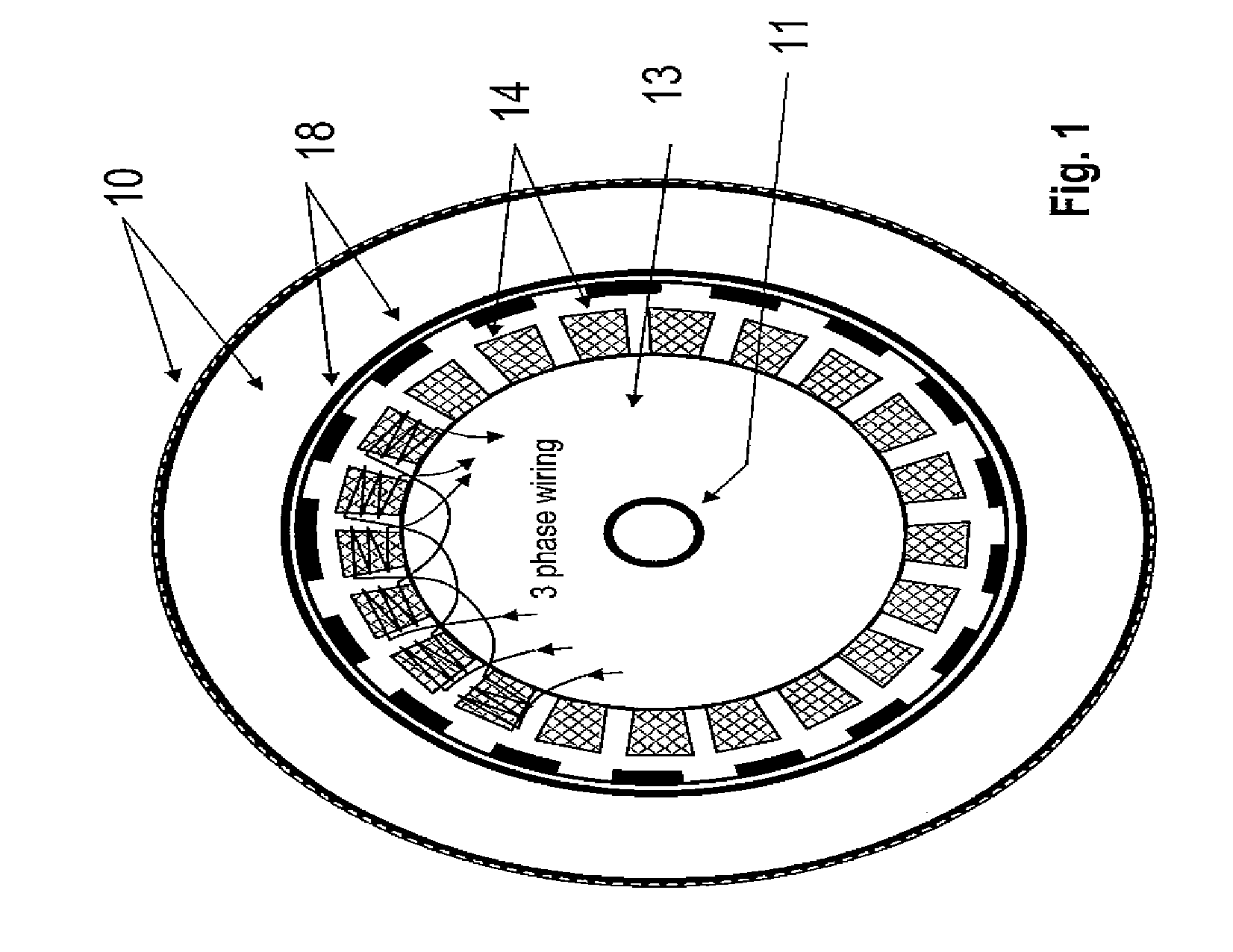
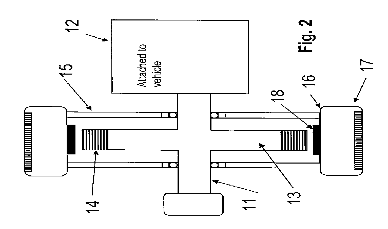
[0059]The integrated wheel and brushless direct current electric motor assembly 10 shown in FIG. 1 has an axle 11 adapted to be attached to the vehicle shown in FIGS. 3 and 4 by a conventional passive suspension consisting of springs and dampers (often called shock absorbers) 12 shown in FIG. 2. Non-rotatably mounted on the axle 11 is a stator 13 which has a plurality of field coils 14 connected as three phase windings adapted to generate a rotating magnetic field. A hub 15 is rotatably mounted on the axle 11 and has an outer rim 16. A tyre 17 is mounted on the outer circumference of the rim 16 and a plurality of rotating permanent magnets 18 are mounted on the inner circumference of the rim in register with the field coils 14 of the stator so as to be rotatably driven thereby.

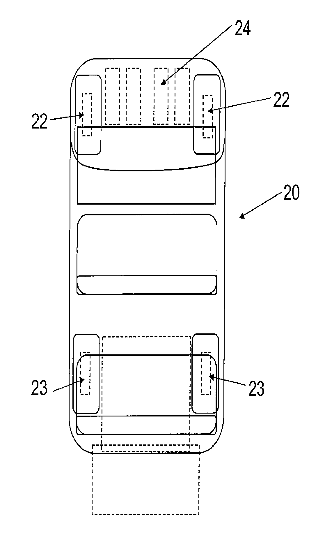
[0060]The low speed electric vehicle 20 shown in FIGS. 3 and 4 has a chassis 21 on which is mounted a front pair of integrated wheel and electric motor assemblies 22 and a rear pair of integrated wheel and ele...


PUM


Abstract

Various embodiments include an electric motor vehicle which does not have any active suspension components, gearbox, differential or other mechanical transmission components, in various embodiments including consists a chassis, at least one pair of integrated wheel and brushless DC electric motor assemblies mounted on the chassis with conventional suspension components including springs and dampers. In various embodiments, a battery pack on the chassis provides power to the integrated wheel and electric motor assemblies; and a control system operates each integrated wheel and motor assembly independently of each other integrated wheel and motor assembly. Various embodiments include the control system has including a master controller connected to the battery pack, and, a separate slave controller connected to the battery pack and to each of the integrated wheel and motor assemblies, as well as the master controller.

Description

TECHNICAL FIELD[0001]This invention relates to electric motor vehicles and more particularly to low speed electric motor vehicles suitable for use as resort cars or golf cars.BACKGROUND ART[0002]Prior art electrical vehicles typically incorporate a brushed motor gearbox train and require a substantial bank of batteries in order to operate. The use of a gearbox train to transfer the power from the motor to the four wheels causes losses in efficiency. Sometimes as much as 50% of the power input to the electric motor is lost before being transferred to the wheels of the vehicle.[0003]Electric vehicles incorporating In-wheel electric motor systems have been developed in the past that have sought to overcome the issue of loss of power and reduced efficiencies associated with conventional electric drive trains. Whilst these in-wheel electric motor vehicles have lower power losses and are more efficient, these vehicles have associated with them, the problem of poor road holding performance...

Claims


Application Information

Patent Timeline
Patent Type & Authority Applications(United States)
IPC IPC(8): B60L15/20B60L11/18
CPCB60K7/0007B60K2001/0411B60K2007/0038B60K2007/0092B60L11/005B60L11/1803B60L2200/26B60L2220/44B60L2260/28Y02T10/7005Y02T10/7011Y02T10/7022Y02T10/7258B60L2200/22B60L50/40B60L50/51Y02T10/70Y02T10/72
Inventor WESTLAKE, BARRY
Owner WESTLAKE BARRY
Learn More