
Integrated process for floating liquefied natural gas pretreatment

a floating, liquefied natural gas technology, applied in separation processes, gaseous fuels, membranes, etc., can solve the problems of affecting the movement of the platform containing the equipment used to purify natural gas, and the maldistribution of liquid within the vessel, so as to mitigate the effect of maldistribution and impact the effectiveness of the amine column

Inactive Publication Date: 2011-12-01
UOP LLC
View PDF23 Cites 21 Cited by
  • Summary
  • Abstract
  • Description
  • Claims
  • Application Information

AI Technical Summary

Benefits of technology

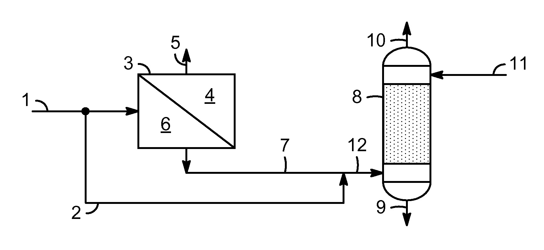
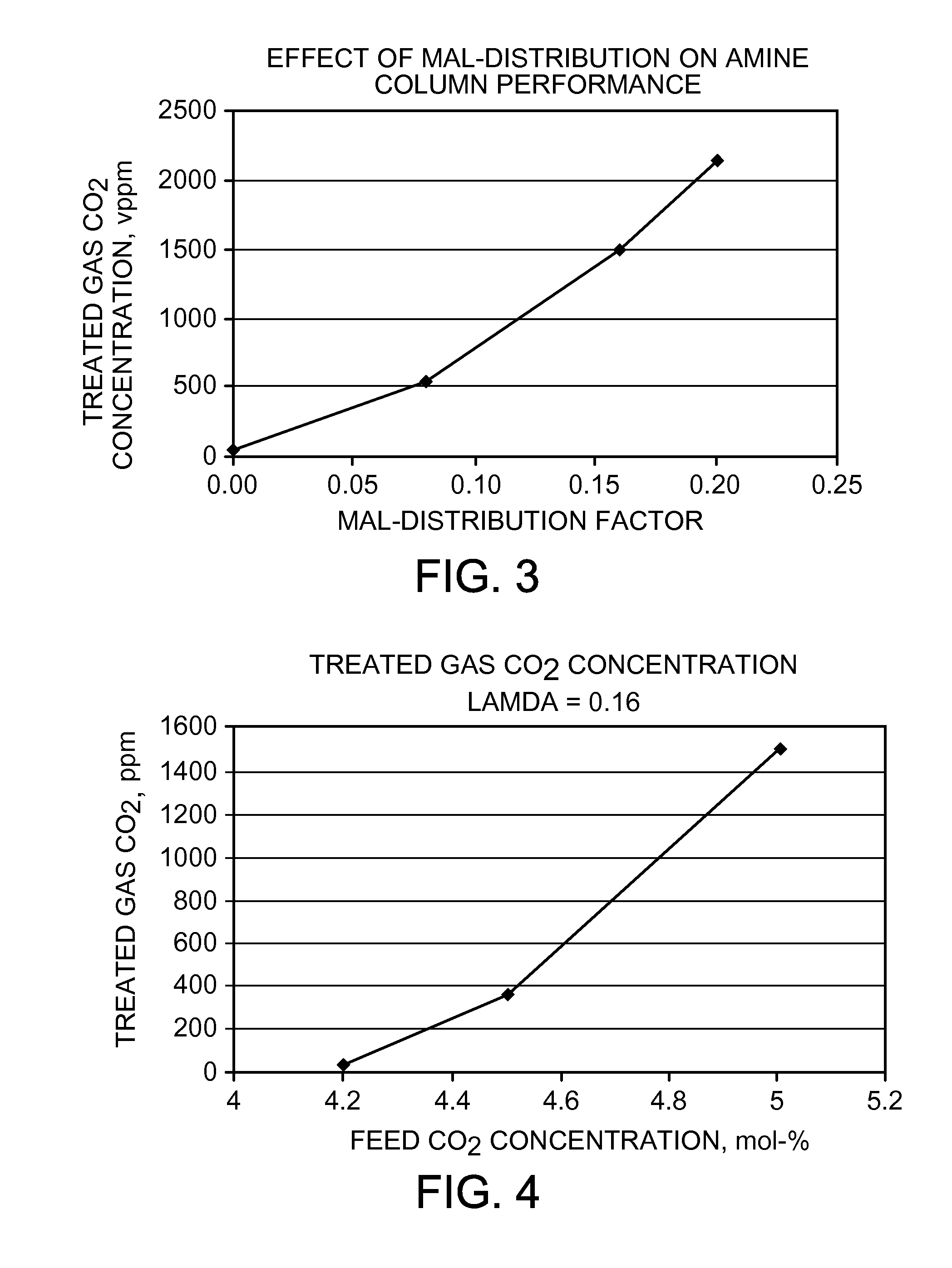
[0005]The present invention, which is intended to be applied on a movable platform such as on a ship or barge, involves a process for removal of acid gases from a raw natural gas stream comprising first sending the raw natural gas stream through a membrane unit containing a membrane for selective separation of acid gases from natural gas and thereby forming a partially purified natural gas stream having an acid gas content lower than the raw natural gas stream. The resulting partially purified natural gas stream is sent to an amine column to be placed in contact with an aqueous amine absorbent contained within the amine column to further remove acid gases and to form a natural gas product effluent having acid gas content less than the partially purified natural gas stream. The platform containing the equipment used to purify natural gas is subject to movement caused by ocean waves and winds. This movement can cause maldistribution of liquid within vessels and can impact the effectiveness of the amine column in removing acid gases such as carbon dioxide and hydrogen sulfide. The present invention deals with this problem by integrating the membrane system and the amine system by changing the membrane operation conditions or process configurations, hence, changing the feed acid gas concentration to the amine absorber, the integrated system can mitigate the effect of maldistribution and deliver the treated gas meeting the feed specifications for LNG liquefaction.

Problems solved by technology

The platform containing the equipment used to purify natural gas is subject to movement caused by ocean waves and winds.
This movement can cause maldistribution of liquid within vessels and can impact the effectiveness of the amine column in removing acid gases such as carbon dioxide and hydrogen sulfide.

Method used


Image

  • Integrated process for floating liquefied natural gas pretreatment
  • Integrated process for floating liquefied natural gas pretreatment
  • Integrated process for floating liquefied natural gas pretreatment

Examples


Embodiment Construction

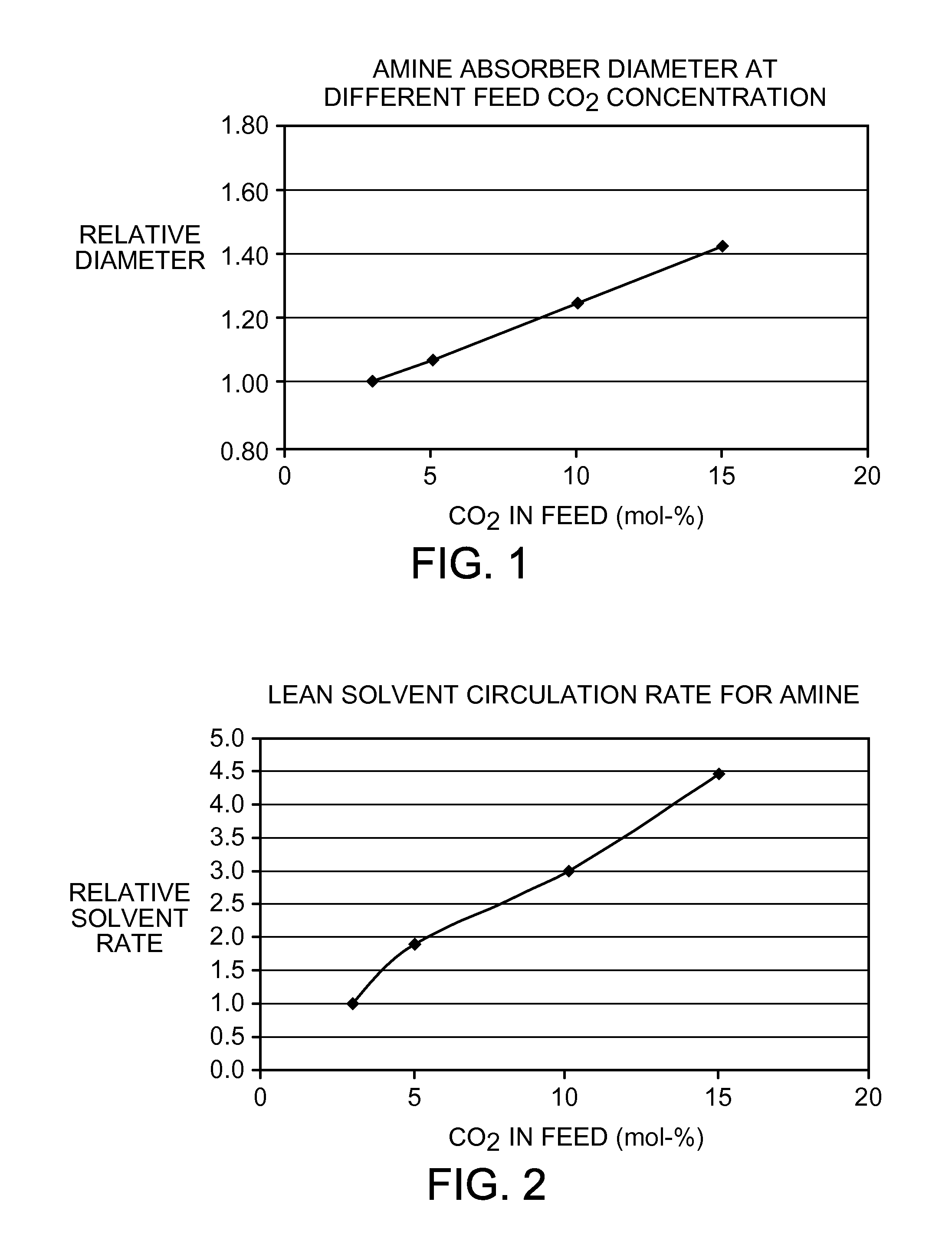
[0014]FIG. 1 shows the relative column diameter needed to treat natural gas streams having CO2 concentrations ranging from about 4 to 15 mol-%. FIG. 2 shows the lean solvent circulation rate that would be needed to treat natural gas having these concentrations of CO2 and would still meet specification requirements of less than 50 parts per million CO2 in the natural gas that is being treated. In an offshore service, this will significantly increase the footprint and weight of the system. There are practical limitations on the maximum size of an amine system that can be built and placed topsides of a ship as part of the pretreatment system. A mobile pretreatment system would need to be designed to treat natural gas feeds streams having differing levels of contamination. The FLNG ship or platform would need to continue to work at various sea conditions of wind and waves. Due to the motion of the ship or other platform, maldistribution of a liquid flow inside the columns and inside pre...


PUM

PropertyMeasurementUnit
Fractionaaaaaaaaaa
Fractionaaaaaaaaaa
Fractionaaaaaaaaaa

Abstract

The present invention provides a membrane / amine column system and process for removing acid gases from natural gas on a floating liquefied natural gas vessel. Several process configurations are provided to deal with a reduction in the effectiveness of the amine column by increasing the amount of acid gases being removed by the membrane system prior to the natural gas being sent to the amine column.

Description

CROSS-REFERENCE TO RELATED APPLICATION[0001]This application claims priority from Provisional Application No. 61 / 349,453 filed May 28, 2010, the contents of which are hereby incorporated by reference.BACKGROUND OF THE INVENTION[0002]The present invention relates to a process for processing natural gas. More particularly, this invention relates to an integrated process for treating natural gas that is to be converted to liquefied natural gas (LNG) on a ship based system.[0003]A new type of vessel is being developed that may revolutionize offshore production of natural gas. The gas industry is currently planning to build a fleet of ships or barges that can be sailed or towed to the site of offshore gas deposits, extract the gas, pretreatment the natural gas to remove impurities, then freeze it to become LNG and then offload the LNG to tankers for shipping to market. It is hoped that these floating liquefied natural gas (FLNG) ships will be cheaper to use than building onshore pretreat...

Claims


Application Information

Patent Timeline
IPC IPC(8): B01D53/22
CPCB01D53/1475B01D53/22B01D53/229B01D2252/204B01D2259/4566Y02C10/06B01D2311/08C10L3/104B01D2311/2626Y02C20/40
Inventor ZHOU, LUBOWEN, XIAOMING
Owner UOP LLC
Learn More