Semiconductor wafer structure and multi-chip stack structure
a technology of multi-chip stack and semiconductor wafer, which is applied in the direction of semiconductor devices, semiconductor/solid-state device details, electrical apparatus, etc., can solve the problems of deformation and cracks in the 3-d multi-chip stack structure, further yield losses in the 3-d multi-chip stack package structure and 3c electronic products, and achieve the effect of enhancing the reliability of the multi-chip stack package structure and minimizing the problem of misalignmen
- Summary
- Abstract
- Description
- Claims
- Application Information
AI Technical Summary
Benefits of technology
Problems solved by technology
Method used
Image
Examples
first embodiment
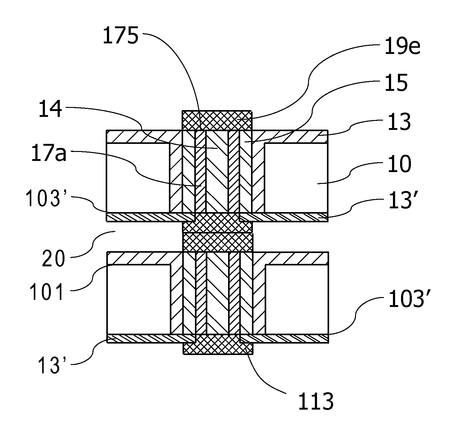
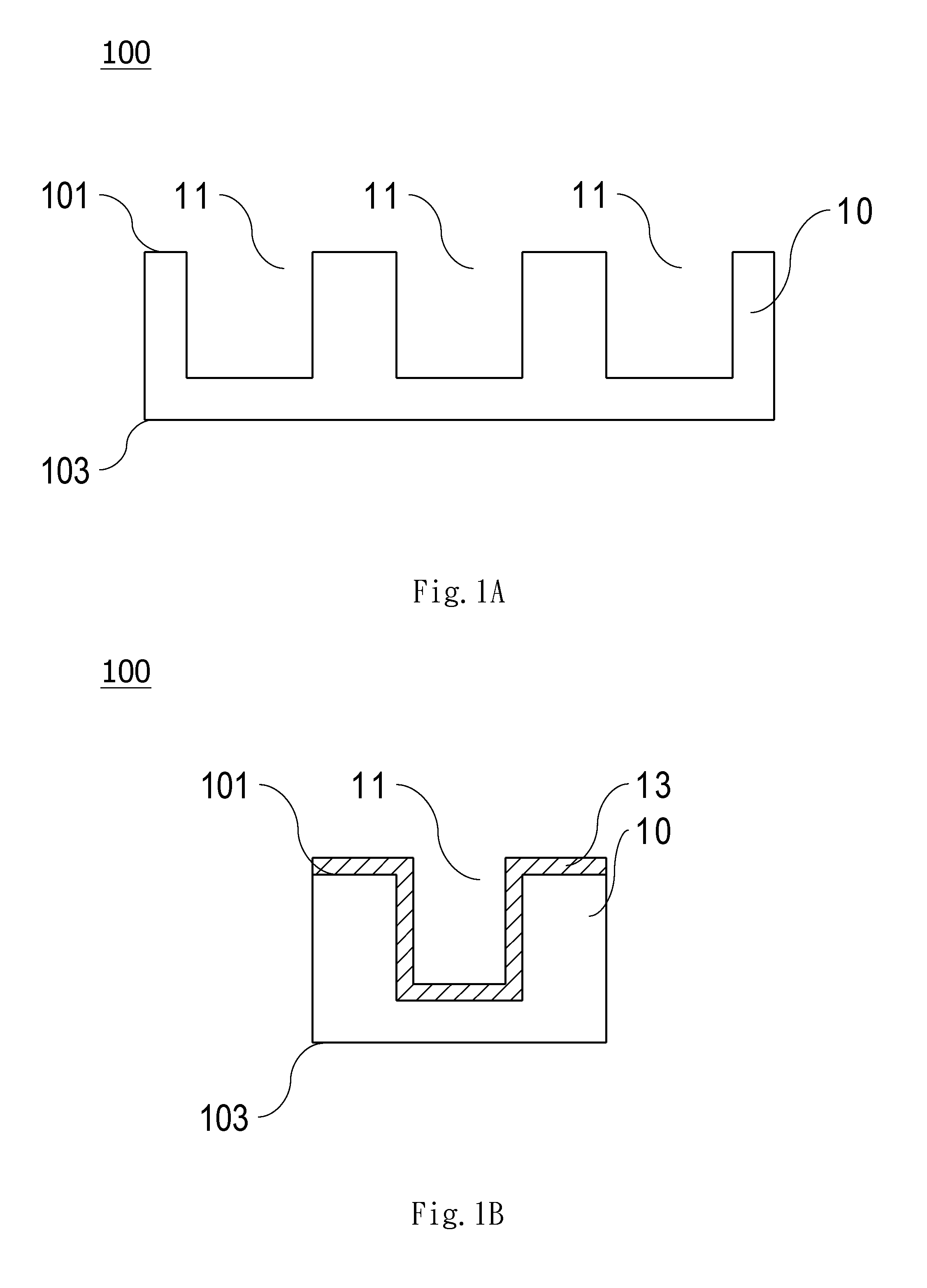
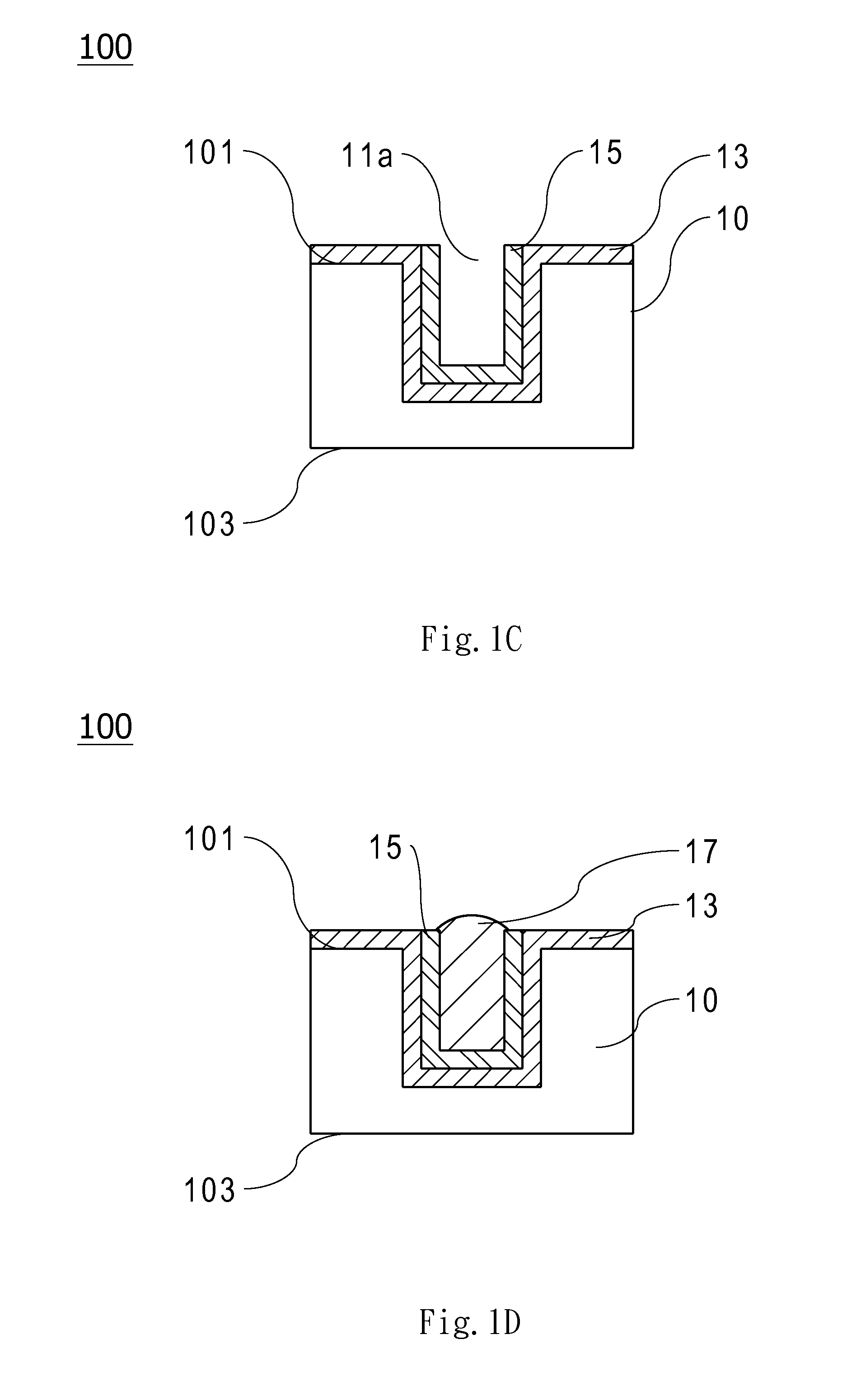
[0056]As shown in FIG. 4A, the present invention provides multi-chip stack structure that is formed by vertically stacking a plurality of semiconductor chips with through-silicon-via electrode structures of FIG. 2A. Please also refer to FIGS. 1B, 1C and 1F. Each of the plurality of semiconductor chips has a first surface 101, a second surface 103′ opposite to the first surface 101 and a plurality of through-silicon holes 11 formed therein. The plurality of through-silicon holes 11 connect the first surface 101 and the second surface 103′. A through-silicon-via electrode structure is formed in each of the plurality of through-silicon holes 11, and the through-silicon-via electrode structure comprises a dielectric layer 13 formed on an inner wall of the through-silicon hole 11, a barrier layer 15 formed on an inner wall of the dielectric layer 13 and defining a vacancy 11a therein, a filling metal layer 17 filled into the vacancy 11a and having a first end 171 and a second end 173 opp...
second embodiment
[0057]Next, as shown in FIG. 4B, the present invention provides multi-chip stack structure which is formed by vertically stacking a plurality of semiconductor chips with through-silicon-via electrode structures of FIG. 2B. In this embodiment, each of the structures on the first surface 101 of the semiconductor chip in FIG. 2B is identical to that in FIG. 2A; the difference is that a soft metal cap 111 is further formed on the second end 173 of each of the plurality of filling metal layers 17 near the lapped second surface 103′ of the semiconductor chip in FIG. 2A. In this embodiment, the horizontal dimension of the soft metal cap 111 is identical to that of the filling metal layer 17. Thus, the multi-chip stack structure is formed by connecting the plurality of soft metal caps 19a / 19b of one of the plurality of semiconductor chips to the plurality of soft metal caps 111 of another semiconductor chip.
third embodiment
[0058]Next, as shown in FIG. 4C, the present invention provides multi-chip stack structure which is formed by vertically stacking a plurality of semiconductor chips with through-silicon-via electrode structures of FIG. 2C. In this embodiment, similar to the semiconductor chip in FIG. 2B, soft metal caps 111 are formed on the second ends 173 of the plurality of filling metal layers 17, but the horizontal dimension of the soft metal cap 111 is larger than that of the filling metal layer 17 so that the soft metal cap 111 overlays the barrier layer 15 and even a portion of the dielectric layer 13′. Thus, the multi-chip stack structure is formed by connecting the plurality of soft metal caps 19a / 19b of one of the plurality of semiconductor chips to the plurality of soft metal caps 111 of another semiconductor chip.
PUM
 Abstract
Description
Claims
Application Information
 - R&D
- Intellectual Property
- Life Sciences
- Materials
- Tech Scout
- Unparalleled Data Quality
- Higher Quality Content
- 60% Fewer Hallucinations
Browse by: Latest US Patents, China's latest patents, Technical Efficacy Thesaurus, Application Domain, Technology Topic, Popular Technical Reports.
© 2025 PatSnap. All rights reserved.Legal|Privacy policy|Modern Slavery Act Transparency Statement|Sitemap|About US| Contact US: help@patsnap.com


