Single-phase ac synchronized motor

a synchronized motor and single-phase technology, applied in the direction of motor/generator/converter stopper, dynamo-electric converter control, instruments, etc., can solve the problem of unstable switchover operation

Inactive Publication Date: 2011-12-01
MINEBEAMITSUMI INC
View PDF4 Cites 19 Cited by
  • Summary
  • Abstract
  • Description
  • Claims
  • Application Information

AI Technical Summary

Benefits of technology

[0008]The present invention has been made in light of the above problem, and it is an object of the present invention to provide a single-phase AC synchronized motor that does not need to smooth rectifier waves and that can perform stable switch-over from a starting operation to a synchronized operation.

Problems solved by technology

However, the single-phase AC synchronized motor disclosed in the Patent Document 1 has the following problems.
In this method, there is a case that the switch-over operation becomes unstable depending on motors or the operation environments of the motors.
Second, in this single-phase AC synchronized motor, since a rectifier wave is smoothed, it makes necessary to have a large and a high-capacity smoothing capacitor.

Method used


Image

  • Single-phase ac synchronized motor
  • Single-phase ac synchronized motor
  • Single-phase ac synchronized motor

Examples


Embodiment Construction

(Motor Structure)

[0024]Preferred embodiments of the present invention will be described with reference to the accompanying drawings.

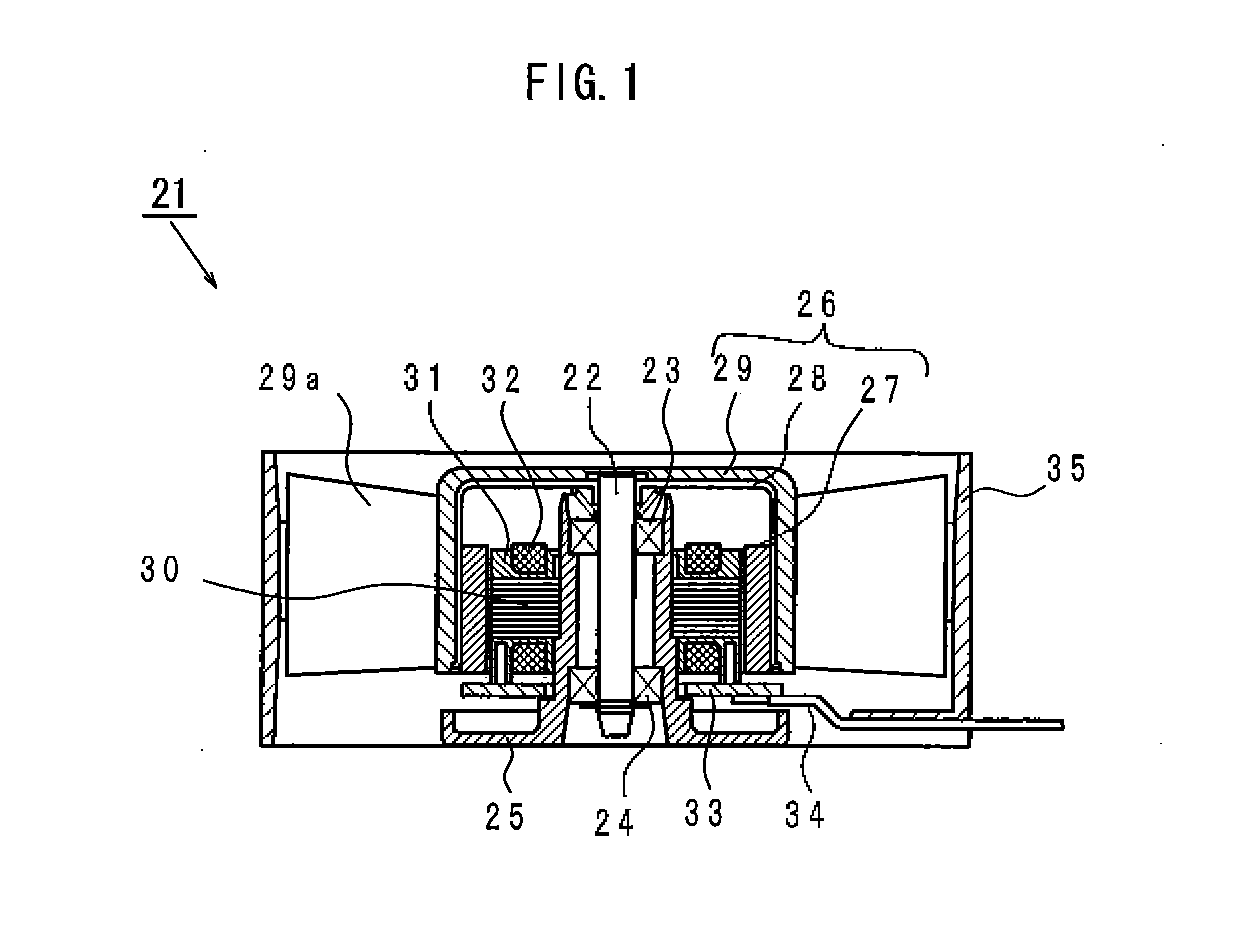
[0025]FIG. 1 is an axial sectional view that schematically shows a motor to which a drive circuit according to the present invention is installed. In FIG. 1, a motor 21 is shown. The motor 21 is an AC fan motor shown as one example of a single-phase AC motor, the motor 21 being provided with a shaft 22 working as a rotary shaft. The shaft 22 is supported by a bearing 23 and a bearing 24. The bearing 23 is installed at the bottom portion of a lower housing 25 while the bearing 24 is installed at the lower housing 25. With this structure, the shaft 22 is installed so as to be rotatable relative to the lower housing 25. Further, the shaft 22 is provided with a permanent magnet rotor 26. The permanent magnet rotor 26 comprises: a rotor yoke 28 where a permanent magnet 27 magnetized by a plurality of magnetic poles is fixed on the inner periphery of the roto...


PUM


Abstract

There is provided a single-phase AC synchronized motor that does not need smooth of rectifier waves but stably performs shift from a starting operation to a synchronized operation. In the motor, based on detected signals of a position sensor, rectified current is reciprocally flowed to each direction of a single-phase coil which starts the motor. The motor includes a start-up operation circuit with a sensor starting period that increases a rotational speed until reaching to a first predetermined rotational speed; and a control device that controls operation of the motor as that shift to synchronized operation is performed when a rotational speed of a permanent magnetic rotor is reached to a second predetermined rotational speed nearby a synchronized rotational speed but not exceeding the synchronized rotational speed, and when the rise and fall of detected signals of the position sensor and the zero-cross point of AC current are approximately correspondent to each other.

Description

BACKGROUND OF THE INVENTION[0001]1. Field of the Invention[0002]The present invention relates to a single-phase AC synchronized motor, in particular, to a single-phase AC synchronized motor as that the single-phase AC synchronized motor is adapted to shift to synchronized operation by means of a synchronized operation circuit at the point of time that the rotational speed of a permanent magnet rotor does not exceed a synchronized rotational speed at a starting operation.[0003]2. Description of the Related Art[0004]In conventional single-phase AC synchronized motors, Japanese Patent No. 4030571 (hereinafter referred to as the “Patent Document 1”) discloses that a starting operation as a DC brushless motor is performed so as to raise the rotational speed of a rotor up to a synchronized rotation. AC current is then applied to a motor coil for switching over to a synchronized operation as an AC synchronized motor.[0005]The single-phase AC synchronized motor disclosed by the Patent Docum...

Claims


Application Information

Patent Timeline
Patent Type & Authority Applications(United States)
IPC IPC(8): H02P1/50H02P1/46H02P6/06H02P6/08H02P6/26
CPCH02P1/465H02P1/50H02P6/22H02P6/181H02P6/008H02P6/26
Inventor SAKAGUCHI, TAKAHIROKOBAYASHI, MASAHIRO
Owner MINEBEAMITSUMI INC
Why Eureka
Try Eureka