
High frequency transformers

a transformer and high frequency technology, applied in transformers, unwanted magnetic/electric effect reduction/prevention, electrical equipment, etc., can solve the problems of reducing performance, serious common mode hf noise problems, and a number of limitations in the use of conventional wound-wire magnetic structures, etc., to achieve the effect of increasing the eddy curren

Active Publication Date: 2011-12-01
HBCC
View PDF12 Cites 11 Cited by
  • Summary
  • Abstract
  • Description
  • Claims
  • Application Information

AI Technical Summary

Benefits of technology

[0010]It is a preferred object of the present invention to provide a high frequency transformer that reduces the EMC and EMI problems of the prior art without increasing the eddy currents.
[0011]It is a preferred object of the present invention to maximise the uniformity of the current and magnetic flux distributions in HF transformers.

Problems solved by technology

The requirement for developing high power density, high efficiency and low profile DC / DC converters and DC / AC inverters has exposed a number of limitations in the use of conventional wound-wire magnetic structures.
However, in high frequency (HF) applications up to 1 MHz, the inter-winding capacitance couples HF noise from the primary winding to the secondary winding and causes serious common mode HF noise problems, as described by L. Tihanyi, Electromagnetic Compatibility in Power Electronics, Piscataway, N.Y., IEEE, 1995, pp.
However, eddy currents are generated in the Faraday shields, which produce a heating effect, lead to demagnetization and reduce performance.
However, it has been found that these Faraday shields still produce a heating effect leading to demagnetization, which prevents optimum performance being achieved.
Another problem with many prior art planar transformers is that they comprise many external connections between the multiple layers, which can be prone to damage.

Method used


Image

  • High frequency transformers
  • High frequency transformers
  • High frequency transformers

Examples


Embodiment Construction

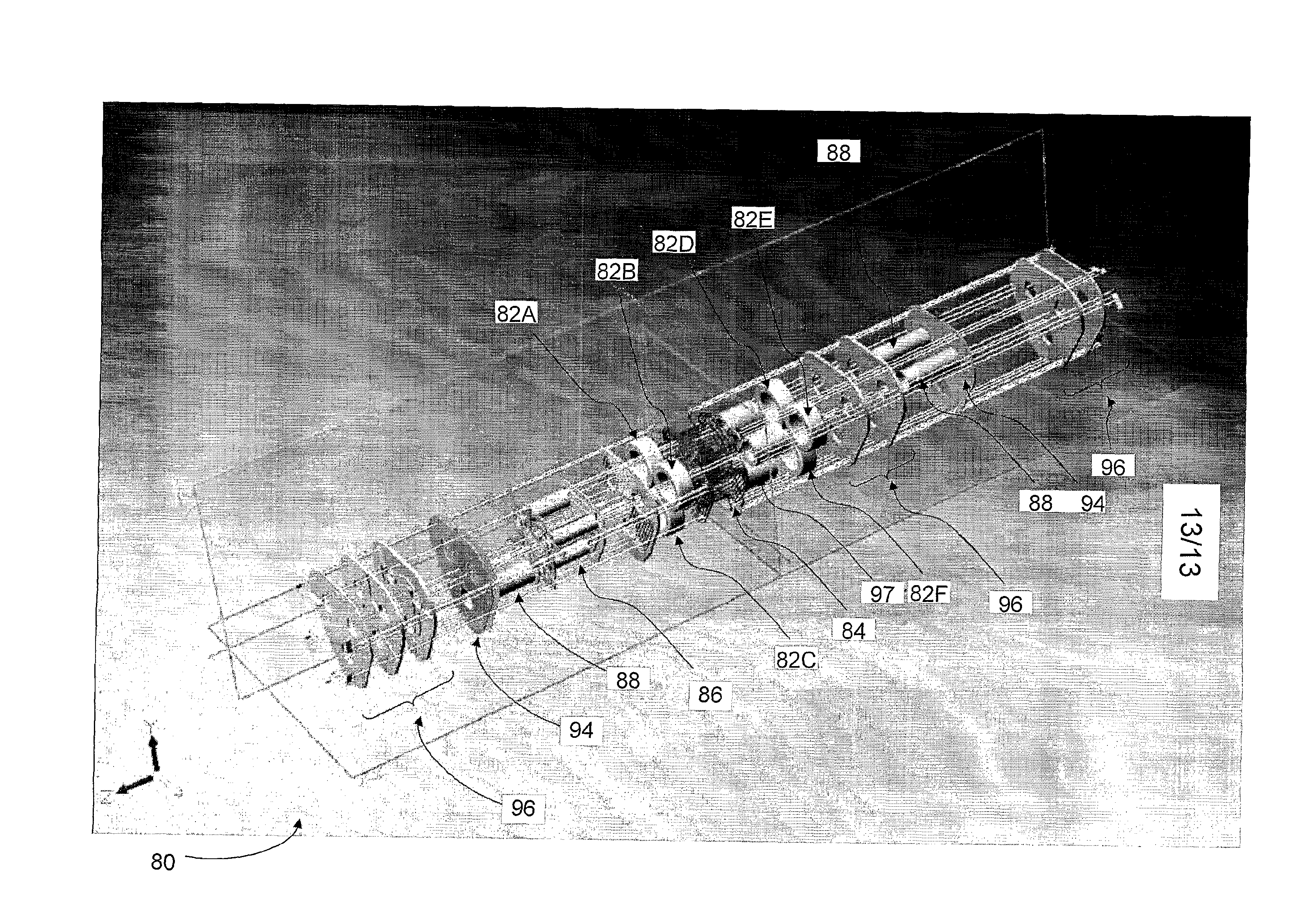
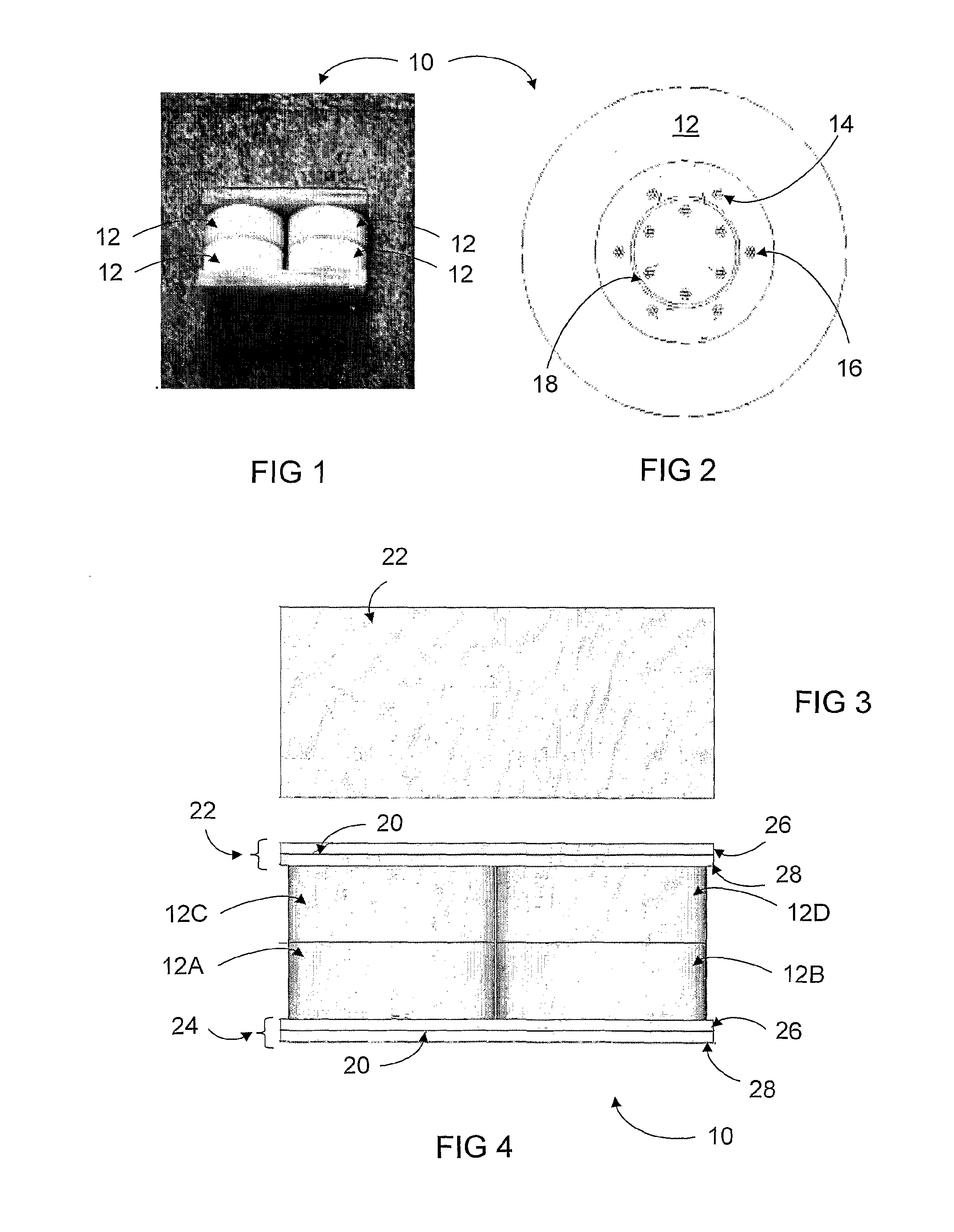
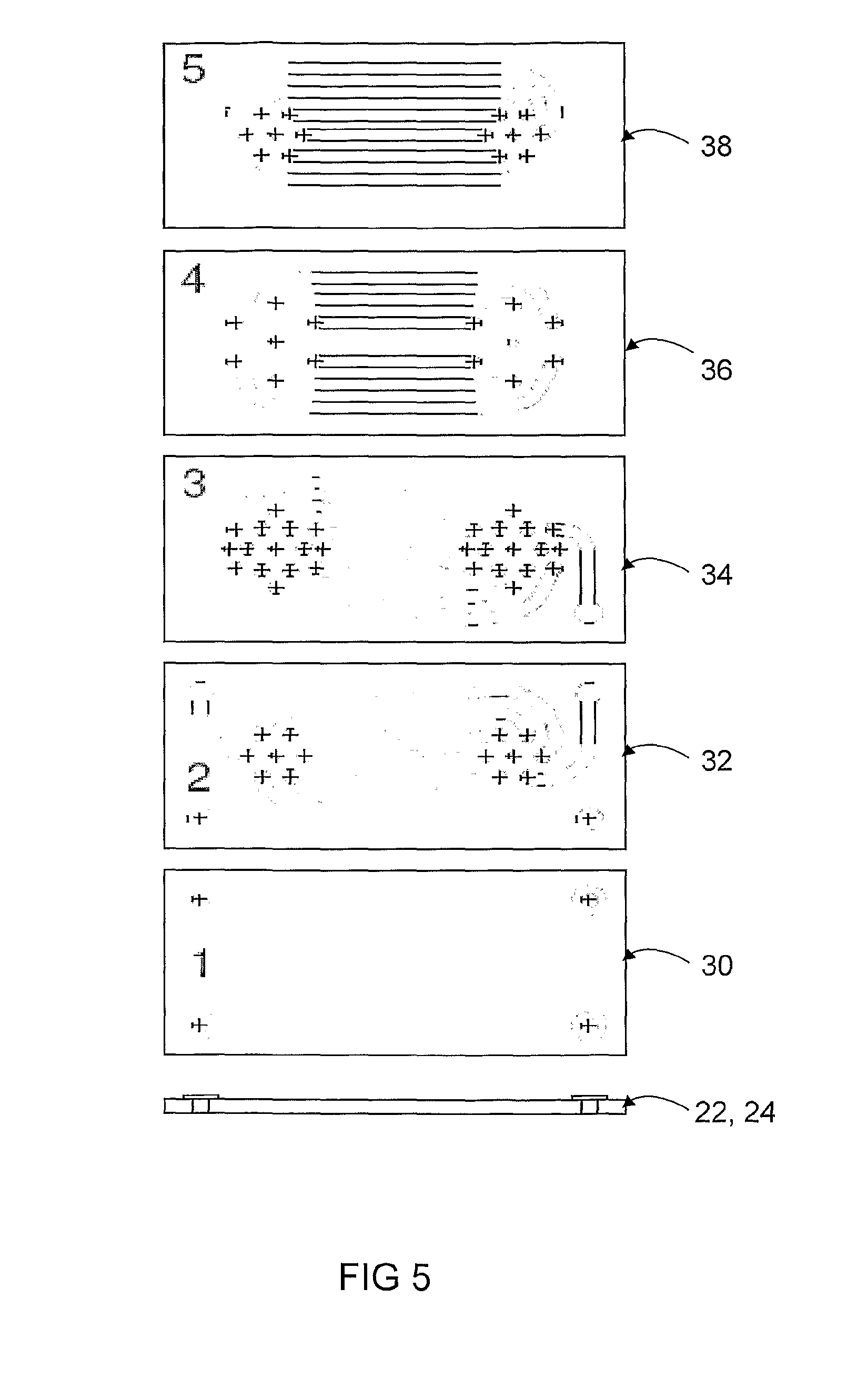
[0075]A high frequency, high power density coaxial transformer and parts thereof according to embodiments of the present invention are shown in FIGS. 1-5. The coaxial transformer 10 comprises at least one magnetic core 12 formed from any suitable conventional magnetic material, such as ferrite ceramics, which are particularly good for high frequency applications. Other possible materials include soft iron, carbonyl iron, silicon alloyed iron and powdered iron and the magnetic core 12 can be laminated to further reduce eddy currents.

[0076]In the embodiments shown in FIGS. 1-5, the coaxial transformer 10 comprises four stacked magnetic cores comprising two adjacent lower magnetic cores 12A, 12B and two adjacent upper magnetic cores 12C, 12D. As shown in FIG. 2, according to some embodiments, the magnetic cores 10 are in the form of hollow cylinders or toroids, which help achieve a highly efficient, low radiation transformer with minimal electromagnetic interference (EMI).

[0077]With re...


PUM


Abstract

High frequency, high power density coaxial, planar and three-phase transformers for converters and inverters are disclosed. One of the coaxial transformers comprises at least one primary winding and at least one secondary winding associated with at least one magnetic core, at least one coaxial Faraday shield between and substantially coaxial with the at least one primary winding and the at least one secondary winding and a substantially planar Faraday shield at one or more ends of the at least one magnetic core.

Description

FIELD OF THE INVENTION[0001]The present invention relates to high frequency transformers. In particular, but not exclusively, embodiments of the present invention relate to high frequency, high power density transformers for DC / DC converters and DC / AC inverters for applications including, but not limited to, renewable energy power conversion systems, switching mode power supplies (SMPS) for communication systems and universal or uninterrupted power supplies (UPS).BACKGROUND TO THE INVENTION[0002]The requirement for developing high power density, high efficiency and low profile DC / DC converters and DC / AC inverters has exposed a number of limitations in the use of conventional wound-wire magnetic structures. A number of high frequency (HF) power transformers have been developed, such as conventional E core or pot core HF power transformers (first generation), planar core power transformers (second generation) and coaxial core power transformers (third generation).[0003]The planar core...

Claims


Application Information

Patent Timeline
IPC IPC(8): H01F27/36
CPCH01F27/2804H01F27/2823H01F27/362H01F2027/348H01F2027/2819H01F2027/2833H01F30/12H01F27/36H01F27/363
Inventor LU, JUN WEI
Owner HBCC
Learn More