Grounded lid for micro-electronic assemblies

a micro-electronic assembly and lid technology, applied in the direction of magnetic/electric field screening, electrical apparatus contruction details, printed circuit non-printed electric components association, etc., can solve problems such as electromagnetic interference, undesired degradation of the performance of an electrical circuit, emi performance degradation,

Inactive Publication Date: 2011-12-01
GLOBALFOUNDRIES INC
View PDF34 Cites 21 Cited by
  • Summary
  • Abstract
  • Description
  • Claims
  • Application Information

AI Technical Summary

Benefits of technology

[0005]According to one embodiment of the present invention, an apparatus for reducing EMI at the micro-electronic-component level includes a substrate having a ground conductor integrated therein. The apparatus includes a micro-electronic component mounted to the substrate. The apparatus further includes an electrically conductive lid mounted to the substrate and thereby forming a physical interface with the substrate, the electrically conductive lid substantially covering the micro-electronic component. The apparatus also includes a conductive link creating an electrical connection between the electrically conductive lid and the ground conductor at the physical interface.
[0006]According to another embodiment of the present invention, a method for reducing EMI at the micro-electronic-component level includes providing a substrate having a ground conductor integrated therein. The method includes mounting a micro-electronic component to the substrate. The method further includes mounting an electrically conductive lid to the substrate and thereby forming a physical interfac

Problems solved by technology

Many electrical circuits operate in harsh and/or noisy environments, which can lead to issues with electromagnetic interference (EMI).
EMI may include any unwanted, spurious, conducted, or radiated signal that can cause an undesire

Method used


Image

  • Grounded lid for micro-electronic assemblies
  • Grounded lid for micro-electronic assemblies
  • Grounded lid for micro-electronic assemblies

Examples


Embodiment Construction

[0017]The present invention provides apparatus and methods for reducing EMI directly at the micro-electronic-component level. It will be readily understood that the components of the present invention, as generally described and illustrated in the drawings herein, could be arranged and designed in a wide variety of different configurations. Thus, the following more detailed description of the embodiments of the invention, as represented in the drawings, is not intended to limit the scope of the invention, as claimed, but is merely representative of certain examples of presently contemplated embodiments in accordance with the invention. The presently described embodiments will be best understood by reference to the drawings, wherein like parts are designated by like numerals throughout.

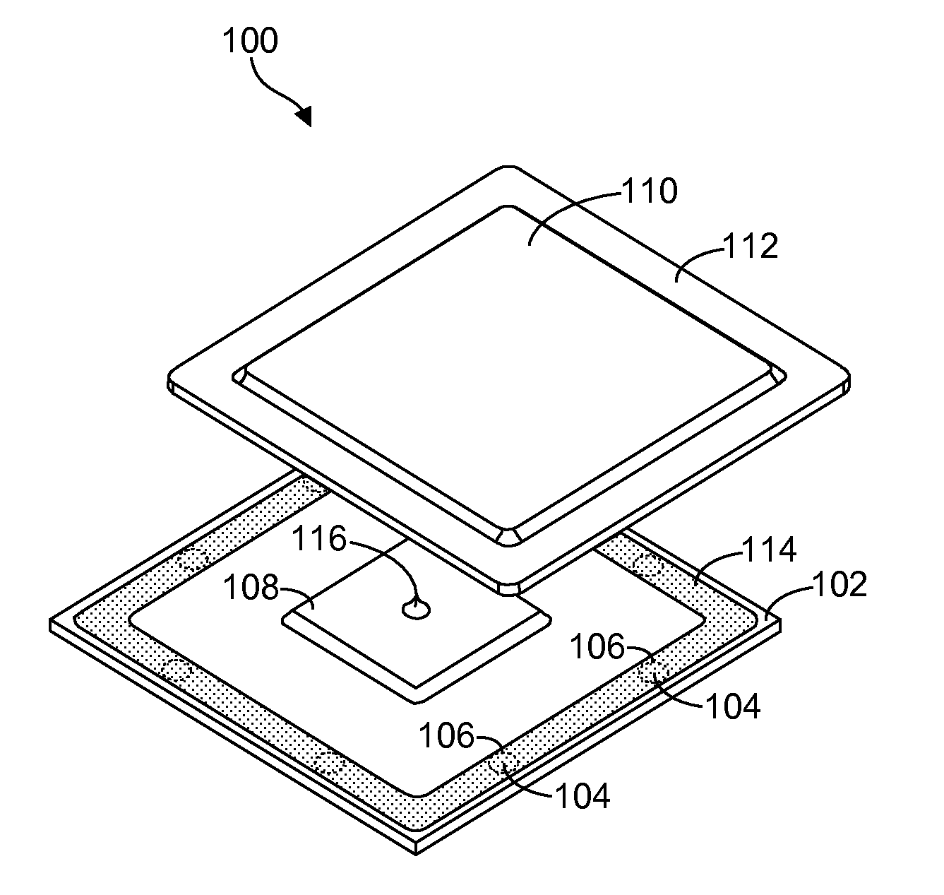
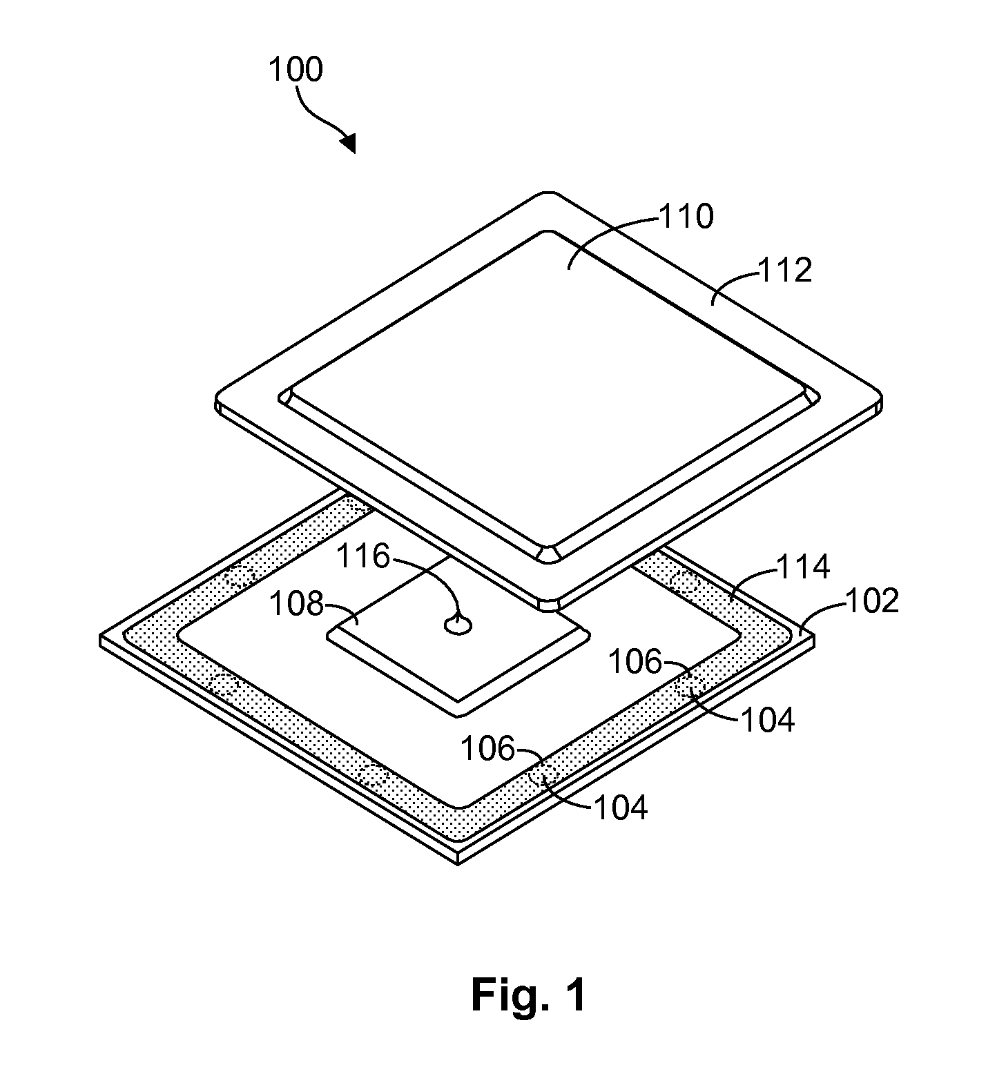
[0018]Referring to FIG. 1, one embodiment of a micro-electronic assembly 100 (or apparatus 100) capable of reducing EMI at the micro-electronic-component level is illustrated. As shown, the micro-elect...


PUM

PropertyMeasurementUnit
Electrical conductivityaaaaaaaaaa
Electrical conductoraaaaaaaaaa

Abstract

An apparatus for reducing EMI at the micro-electronic-component level includes a substrate having a ground conductor integrated therein. A micro-electronic component such as an integrated circuit is mounted to the substrate. An electrically conductive lid is mounted to the substrate, thereby forming a physical interface with the substrate. The electrically conductive lid substantially covers the micro-electronic component. A conductive link is provided to create an electrical connection between the electrically conductive lid and the ground conductor at the physical interface.

Description

BACKGROUND[0001]The present invention relates to apparatus and methods for mitigating electromagnetic interference (EMI) in electrical circuits.[0002]Electrical circuits such as integrated circuits are used in a wide variety of different environments. As a result, special efforts are needed to develop electrical circuits that can function properly in their intended operational environments. Many electrical circuits operate in harsh and / or noisy environments, which can lead to issues with electromagnetic interference (EMI). EMI may include any unwanted, spurious, conducted, or radiated signal that can cause an undesired degradation in the performance of an electrical circuit. Electromagnetic compatibility (EMC), on the other hand, is the ability of an electrical circuit to function as designed, without malfunctioning or exhibiting unacceptable performance degradation as a result of EMI that may be present in its operating environment. Examples of EMI performance degradation include a...

Claims


Application Information

Patent Timeline
IPC IPC(8): H05K1/00H05K13/00
CPCH01L2224/32225H01L23/10H01L2924/15311H01L2224/73204H01L2924/10253H01L2224/16225H01L2224/73253H01L23/055H01L23/552Y10T29/49117H01L2924/16251H05K9/0009H01L2924/00H01L2924/00014H01L2924/00011H01L2224/0401
Inventor BEAUMIER, MARTINBLANDER, ALEXANDREGAGNON, PASCALEGAYNES, MICHAEL A.GIGUERE, ERICSALVAS, ERICTOUSIGNANT, LUC
Owner GLOBALFOUNDRIES INC
Why Eureka
Try Eureka