

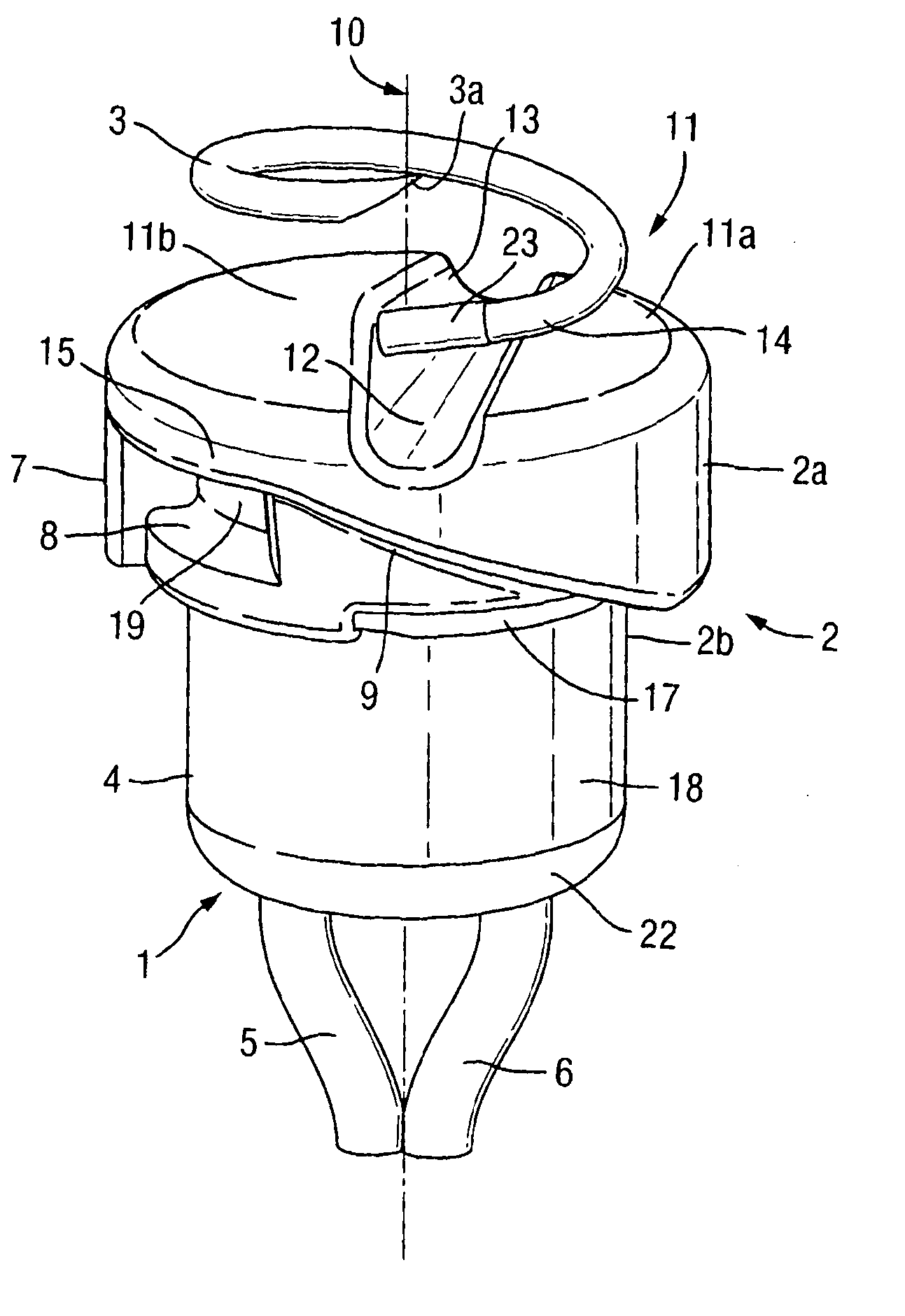
Fetal electrode assembly and fetal electrode
a technology of fetal electrodes and fetal electrodes, which is applied in the field of improved fetal electrode assembly, can solve the problems of fetal electrodes being damaged, fetal electrodes being difficult to attach properly and remove, and fetal electrodes being difficult to unscrew themselves, so as to improve the control and fitting of fetal electrodes.
- Summary
- Abstract
- Description
- Claims
- Application Information
AI Technical Summary
Benefits of technology
Problems solved by technology
Method used
Image

Examples
Embodiment Construction
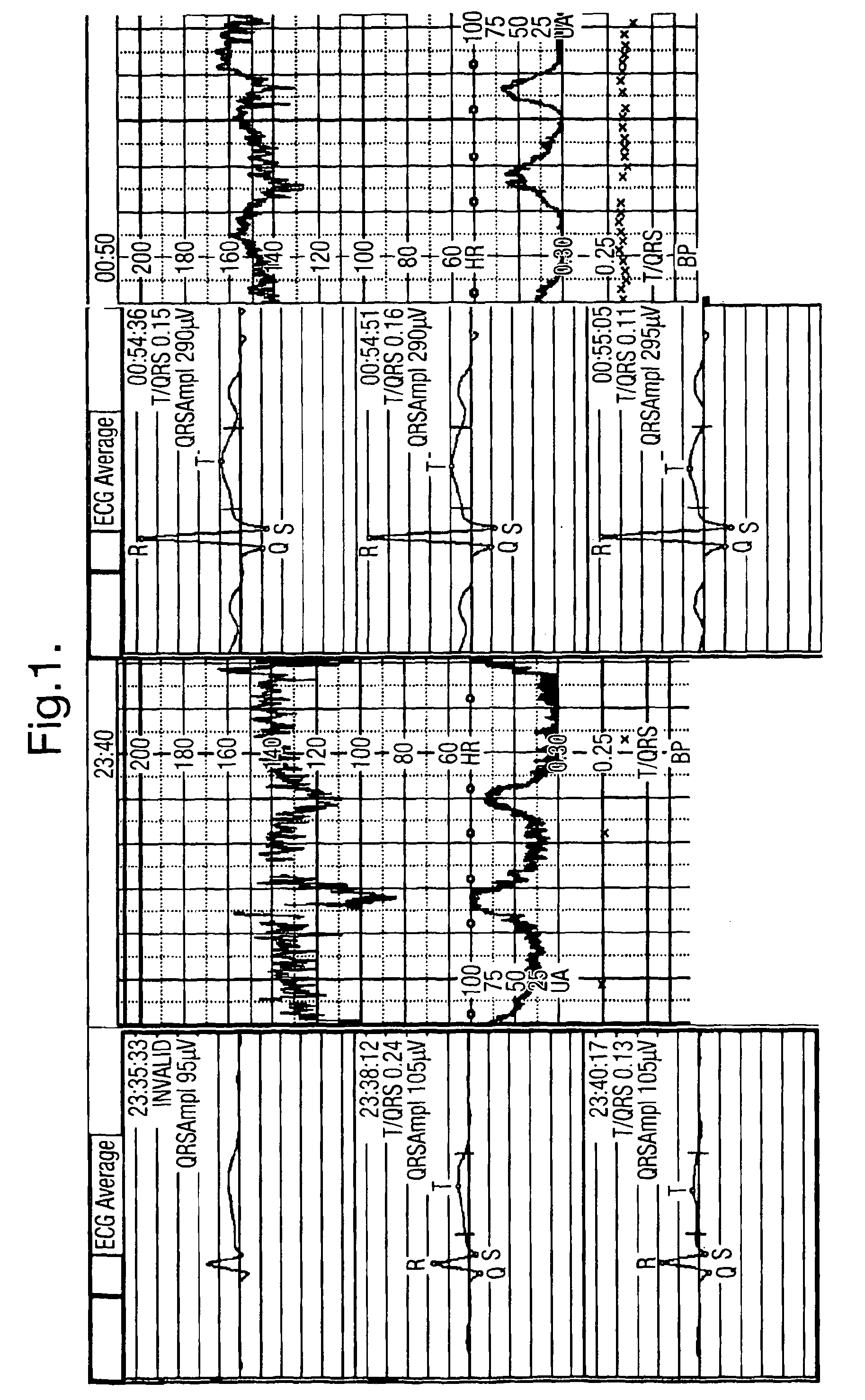
[0068]The left hand side of FIG. 1 illustrates a set of ECG traces for a real case where the fetal electrode eventually fell off the fetus. The left hand boxes show the initial averaged ECG complexes and the corresponding CTG trace. With the poor application, the QRS-amplitude is around 100 μV. The boxes on the right display the situation about one hour later when the electrode has been adequately re-applied. The QRS-amplitude is then instead about 290 μV, an improvement of three times on the earlier trace. Thus the importance of having a correct and reliable fitting of the fetal electrode is apparent.
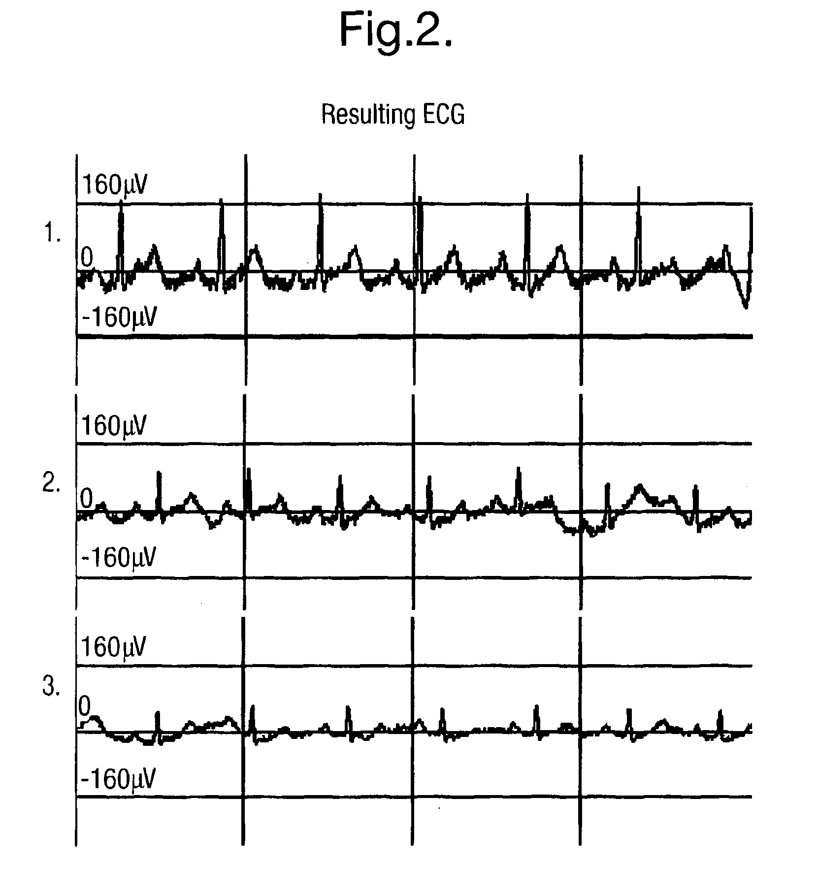
[0069]FIG. 2 illustrates the resulting ECG traces for a fetal scalp electrode which in the first trace, has been near perfectly applied, in the second trace has been unscrewed one quarter of a turn, and in the third case has been unscrewed half of a turn. The reduction in the amplitude of the fECG signals as a result of the fetal scalp electrode unwinding, can be clearly seen from the ...
PUM
 Abstract
Description
Claims
Application Information