Robotically-controlled endoscopic accessory channel

a robotic control and accessory channel technology, applied in the field of robotic control of endoscopic accessory channels, can solve the problems of inability to suitably achieve user-feedback effects, complicated integration of controls for articulating and actuating the working end of an endoscopic device, and interfere with the flexibility of the sha

Active Publication Date: 2011-12-01
CILAG GMBH INT
View PDF5 Cites 712 Cited by
  • Summary
  • Abstract
  • Description
  • Claims
  • Application Information

AI Technical Summary

Benefits of technology

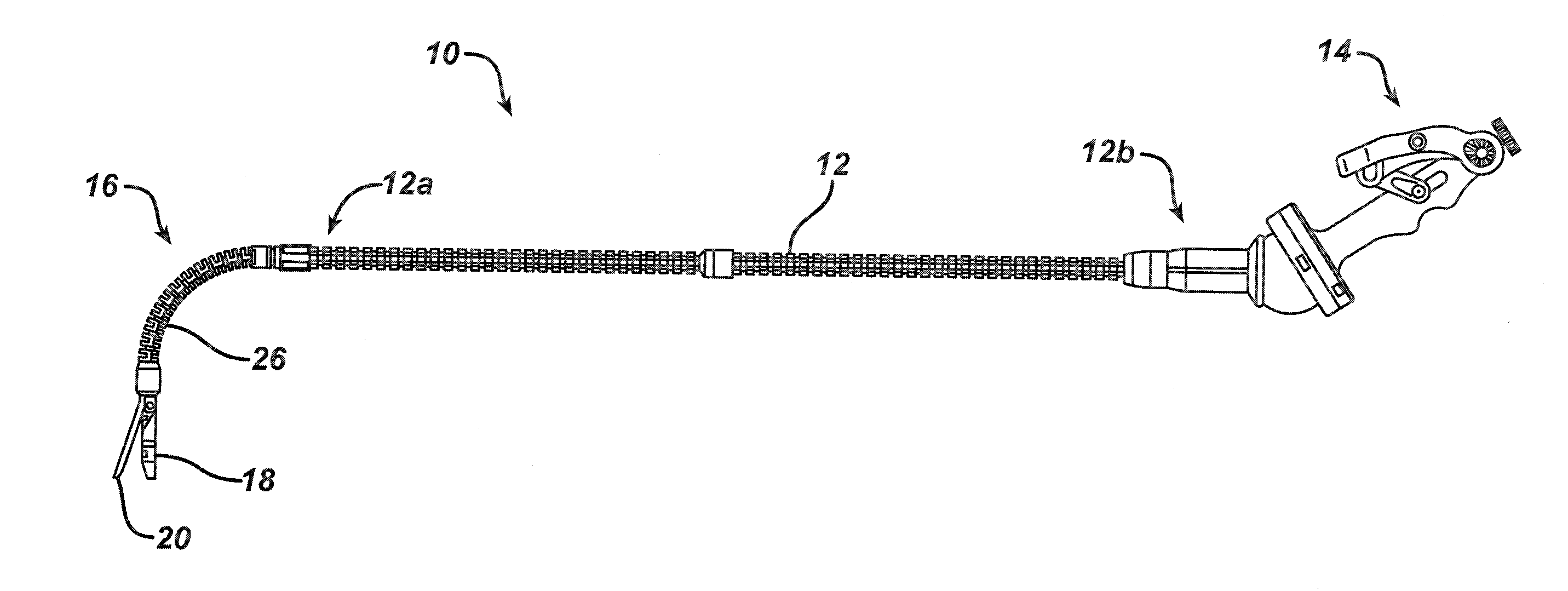
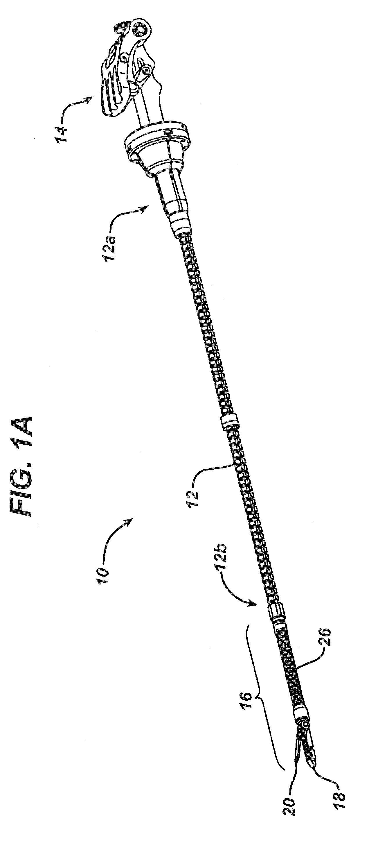
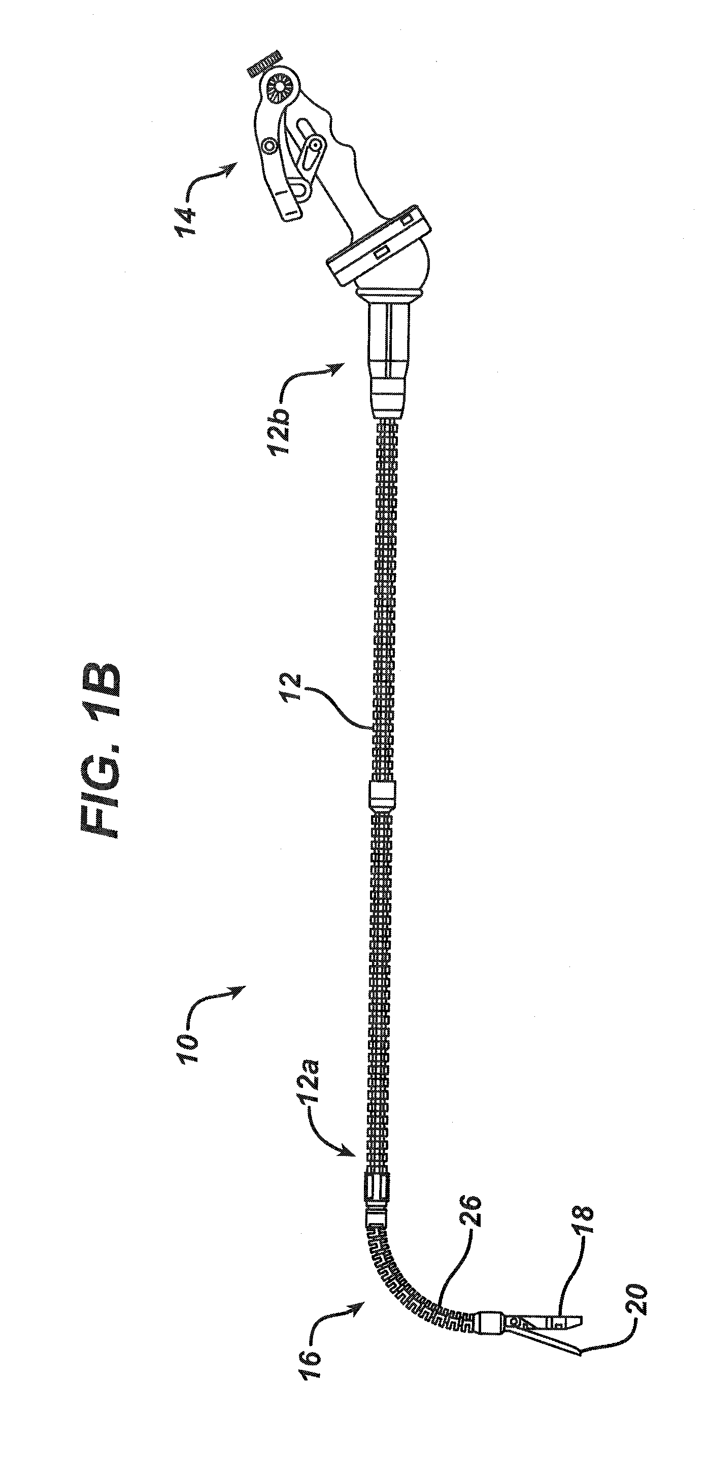
[0010]The present invention also provides an endoscopic system having an elongate sleeve configured to be disposed around an endoscope, and an accessory channel removably matable to the elongate sleeve. The accessory channel can have an inner lumen extending therethrough between proximal and distal ends thereof for receiving a tool, a flexible portion formed on a distal portion thereof and being made flexible by a plurality of slits formed therein, and at least one handle coupled to the proximal end thereof and operatively associated with the flexible portion such that the handle(s) is configured to cause the flexible portion to articulate in at least one plane. The handle(s) can be operatively associated with the flexible portion by at least one cable, and the handle(s) can be configured to axially move the cable(s) relative to the accessory channel to cause the cable(s) to apply tension to the flexible portion of the accessory channel such that the flexible portion articulates in at least one plane. In one embodiment, the device can include a single handle configured to cause the flexible portion to articulate in multiple planes. The single handle can include a st

Problems solved by technology

Integration of the controls for articulating and actuating a working end of an endoscopic device tend to be complicated by the use of a flexible shaft and by the size constraints of an endoscopic instrument.
Generally, the c

Method used


Image

  • Robotically-controlled endoscopic accessory channel
  • Robotically-controlled endoscopic accessory channel
  • Robotically-controlled endoscopic accessory channel

Examples


Embodiment Construction

[0161]Applicant of the present application also owns the following patent applications that have been filed on even date herewith and which are each herein incorporated by reference in their respective entireties:

[0162]U.S. patent application Ser. No. ______, entitled “Surgical Instrument With Wireless Communication Between a Control Unit of a Robotic System and Remote Sensor”, Attorney Docket No. END5924USCIP2 / 060339CIP2;

[0163]U.S. patent application Ser. No. ______, entitled “Robotically-Controlled Disposable Motor Driven Loading Unit”, Attorney Docket No. END6213USCIP1 / 070330CIP1;

[0164]U.S. patent application Ser. No. ______, entitled “Robotically-Controlled Motorized Surgical Instrument”, Attorney Docket No. END6416USCIP1 / 080205CIP1;

[0165]U.S. patent application Ser. No. ______, entitled “Robotically-Controlled Surgical Stapling Devices That Produce Formed Staples Having Different Lengths”, Attorney Docket No. END5675USCIP6 / 050504CIP6;

[0166]U.S. patent application Ser. No. _____...


PUM


Abstract

Devices and systems are provided for controlling movement of a working end of a surgical device by means of a robotic system. In one embodiment, systems and devices are provided for moving an end effector on a distal end of a surgical fastening device. Movement can include rotational movement of the end effector about an axis of the shaft, articulation of the end effector relative to the shaft, and actuation of an end effector, e.g., closing, firing, and/or cutting.

Description

CROSS-REFERENCE TO RELATED APPLICATIONS[0001]This non-provisional patent application is a continuation-in-part patent application of and claims the benefit of U.S. patent application Ser. No. 11 / 277,324, filed Mar. 23, 2006, U.S. Patent Publication No. US 2007 / 0225562-A1, the disclosure of which is herein incorporated by reference in its entirety.FIELD OF THE INVENTION[0002]The present invention relates broadly to methods and devices for controlling movement of a working end of a surgical device.BACKGROUND OF THE INVENTION[0003]Endoscopic surgical instruments are often preferred over traditional open surgical devices since the use of a natural orifice tends to reduce the post-operative recovery time and complications. Consequently, significant development has gone into a range of endoscopic surgical instruments that are suitable for precise placement of a working end of a tool at a desired surgical site through a natural orifice. These tools can be used to engage and / or treat tissue...

Claims


Application Information

Patent Timeline
IPC IPC(8): A61B17/00
CPCA61B17/072A61B2019/5229A61B17/115A61B17/32053A61B19/026A61B19/0287A61B19/2203A61B19/5225A61B2017/00199A61B2017/0023A61B2017/003A61B2017/00327A61B2017/0042A61B2017/00473A61B2017/00477A61B2017/00685A61B2017/00734A61B2017/0688A61B2017/07235A61B2017/07242A61B2017/07264A61B2017/07271A61B2017/07278A61B2017/2905A61B2017/2919A61B2017/2923A61B2017/2927A61B2017/2947A61B2017/320052A61B2019/2242A61B17/07207A61B1/0052A61B1/0058A61B17/068A61B17/320016A61B34/30A61B34/71A61B50/30A61B50/36A61B90/37A61B2017/00057A61B2017/00309A61B2017/00314A61B2017/00323A61B2017/00367A61B2017/291A61B2017/2933A61B2017/2937A61B2017/2946A61B2034/306A61B2090/0811A61B2090/372A61B1/00042
Inventor SPIVEY, JAMES T.ORTIZ, MARK S.SHELTON, IV, FREDERICK E.
Owner CILAG GMBH INT
Why Eureka
Try Eureka